
Floating connector and connector assembly using the same

A floating connector and connector assembly technology, applied in the direction of connection, coupling device, base/shell, etc., can solve the problems of low assembly efficiency, high failure rate, complex structure of floating connector, etc., and achieve the effect of solving complex structure

Active Publication Date: 2019-02-15
CHINA AVIATION OPTICAL-ELECTRICAL TECH CO LTD
View PDF7 Cites 0 Cited by
  • Summary
  • Abstract
  • Description
  • Claims
  • Application Information

AI Technical Summary

Problems solved by technology

[0005] The purpose of the present invention is to provide a floating connector to solve the problems of the current floating connectors with complex structure, low assembly efficiency and high failure rate; in addition, the purpose of the present invention is to provide a connection using the floating connector Components

Method used


Image

  • Floating connector and connector assembly using the same

Examples


Embodiment Construction

[0027] Embodiments of the present invention will be further described below in conjunction with the accompanying drawings.

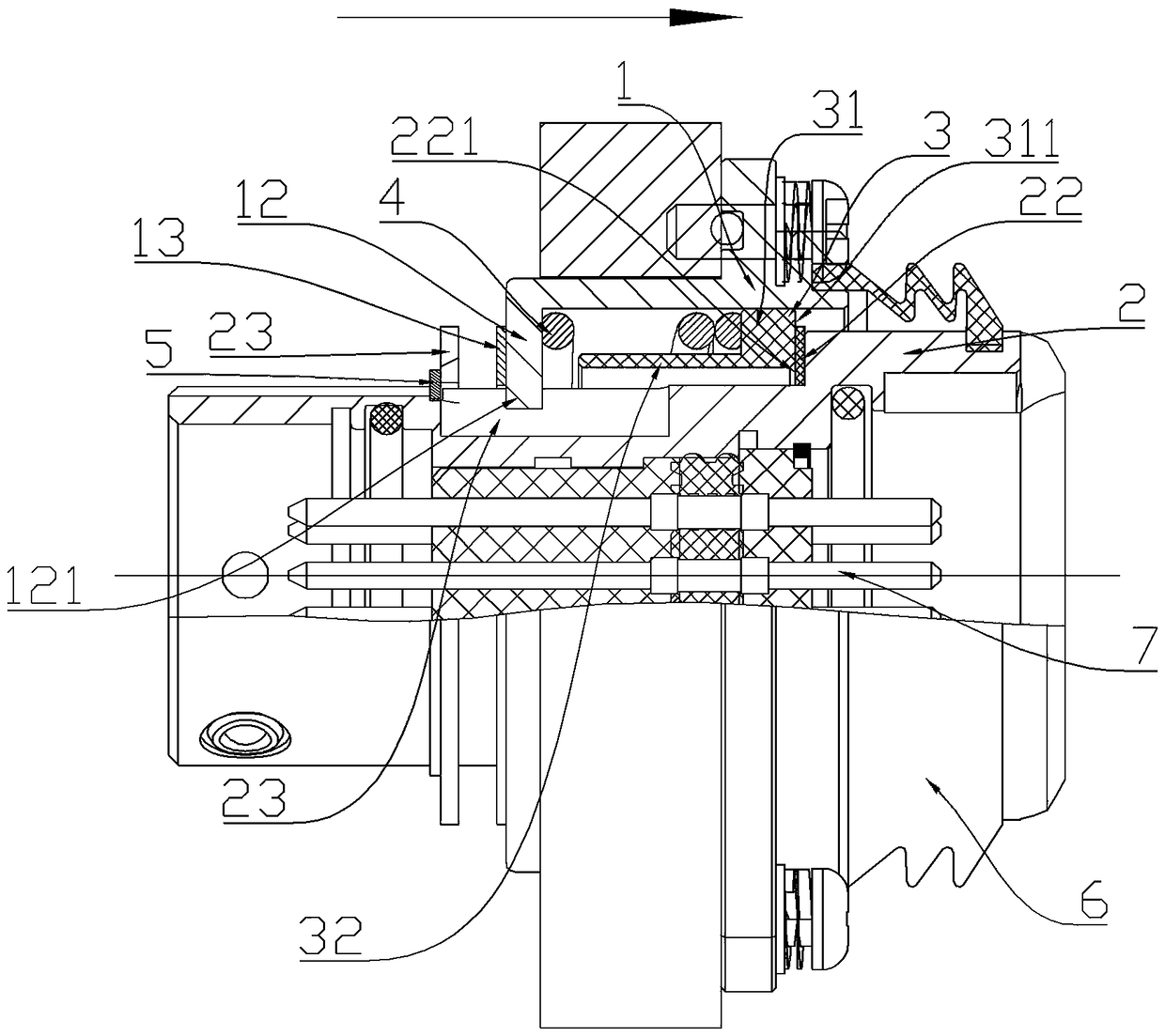
[0028] Specific embodiments of the floating connector of the present invention, such as figure 1 As shown, the floating connector includes a fixed housing 1 and a floating housing 2 whose front end is a plug-in terminal. The floating housing 2 is provided with a plug-in contact 7 . In this embodiment, both the fixed housing 1 and the floating housing 2 are cylindrical structures whose axes extend along the front-to-back direction. The housing 2 can float axially and radially.

[0029] The floating connector also includes a floating sleeve 3 between the fixed housing 1 and the floating housing 2. The floating sleeve 3 and the inner wall of the fixed housing 1 slide and fit along the front and rear directions. The outer sleeve of the floating sleeve 3 is set as a floating sleeve 3 Return spring 4 providing forward force. The back-moving spring 4 extends...


PUM


Abstract

The invention relates to the field of connectors, in particular to a floating connector and a connector component using the floating connector. The floating connector comprises a fixing housing and a floating housing of which the front end is an inserting end, the axial line of the floating housing extends in the front and rear direction, the floating housing is arranged on the fixing housing and can float in the axial direction and the radial direction, the floating connector further comprises a floating sleeve located between the fixing housing and the floating housing, the floating sleeve slidably matches with the fixing housing in the front and rear directions, an elastic resetting piece providing forward acting force for the floating sleeve is arranged between the floating sleeve and the fixing housing, the floating housing is provided with a floating housing positioning surface, the floating sleeve is provided with a floating sleeve positioning surface matched with the floating housing positioning surface, and is installed on the floating housing positioning surface in an jacked mode through the elastic resetting piece, and the floating housing positioning surface and / or the floating sleeve positioning surface are / is self-lubricating surfaces or a self-lubricating surface. The problems are solved that currently, the floating connector is complicated in structure, low in assembling efficiency and high in fault rate.

Description

technical field [0001] The invention relates to the field of connectors, in particular to a floating connector and a connector assembly using the floating connector. Background technique [0002] In the design of board-to-board docking products, floating connector components are often used. The floating connector components include plugs and sockets. The plugs and sockets are inserted to transmit optical signals. The action of the manipulator realizes the insertion of the plug and socket on the opposite board. Since there is a certain error in the operation of the manipulator, the floating amount between the plug and the socket compensates the operation error of the manipulator to realize the normal insertion of the plug and the socket. [0003] Existing floating connectors such as "Floating Connector and Connector Assembly Using the Floating Connector" disclosed in the Chinese patent application with the publication number CN105655806A and the publication date of 2016.06.08...

Claims


Application Information

Patent Timeline
Patent Type & Authority Patents(China)
IPC IPC(8): H01R12/91H01R13/46
CPCH01R12/91H01R13/46
Inventor 邹宏飞崔艳磊柳先波
Owner CHINA AVIATION OPTICAL-ELECTRICAL TECH CO LTD
Learn More