
Wireless charging equipment

A technology of wireless charging equipment and charging equipment, which is applied to electrical components, circuit devices, etc., can solve the problems of reduced transmission efficiency, small space area, short energy transmission distance, etc., and achieves the effect of improving stability and receiving power stability.

Inactive Publication Date: 2017-06-13
SHENZHEN TINNO WIRELESS TECH
View PDF3 Cites 2 Cited by
  • Summary
  • Abstract
  • Description
  • Claims
  • Application Information

AI Technical Summary

Problems solved by technology

At present, some wireless charging devices use a wireless charging platform based on inductive coupling. The disadvantage is that the receiving coil and the transmitting coil cannot be separated, and the energy transmission distance is relatively short.
Some wireless charging devices use anti-parallel coils to overcome the problem of reduced transmission efficiency due to distance changes, but the coil structure must be coaxial with the receiving coil and the transmitting coil, and the spatial area for stable energy transmission is small

Method used


Image

  • Wireless charging equipment
  • Wireless charging equipment
  • Wireless charging equipment

Examples


Embodiment Construction

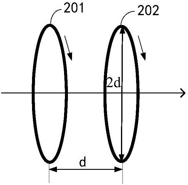
[0022] see figure 1 , figure 1 It is a schematic structural diagram of an embodiment of the wireless charging device of the present invention, the wireless charging device includes:

[0023] The power supply circuit 10 ; specifically, the power supply circuit 10 includes a resonant circuit 100 for providing an alternating current with a first resonant frequency to the Helmholtz coil 12 . In a practical application scenario, the power supply circuit 10 also includes a rectification and filtering sub-circuit (not shown in the figure), and the AC mains (220V) is converted into a direct current by the rectification and filtering sub-circuit and input to the resonant circuit 100, and the resonant circuit 100 inverts the direct current into The alternating current of the first resonance frequency is sent to the Helmholtz coil 12 .

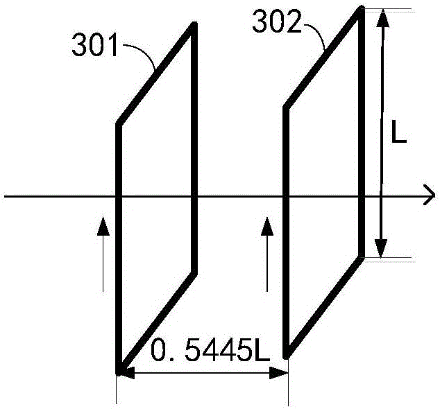
[0024] At least two Helmholtz coils 12 arranged parallel to each other and coaxially, coupled to the power supply circuit 10, are the first coil 120 a...


PUM


Abstract

The invention discloses wireless charging equipment. The charging equipment comprises a power supply circuit and at least two parallel and coaxially arranged Helmholtz coils, wherein the two Helmholtz coils are coupled to the power supply circuit, the Helmholtz coils are a first coil and a second coil respectively, and after electrification, uniform magnetic field areas exist between the first coil and the second coil; if the first coil and the second coil are circular coils, the first coil and the second coil have the same number of turns and radius, and the distance between the first coil and the second coil is identical to the radius; if the first coil and the second coil are square coils, the first coil and the second coil have the same number of turns and side length, and the distance between the first coil and the second coil is 0.5445 time of the side length. Through the method, the wireless charging equipment can improve stability of wireless energy transmission in a certain space region.

Description

technical field [0001] The invention relates to the field of wireless charging, in particular to a wireless charging device. Background technique [0002] Wireless charging equipment has gradually begun to enter all aspects of people's daily life, especially restricted by the development of battery technology, the emergence of wireless charging has brought earth-shaking changes to people's production and life. At present, some wireless charging devices use a wireless charging platform based on inductive coupling. The disadvantage is that the receiving coil and the transmitting coil cannot be separated, and the energy transmission distance is relatively short. Some wireless charging devices use anti-parallel coils to overcome the problem of reduced transmission efficiency due to distance changes, but the coil structure must be coaxial with the receiving coil and the transmitting coil, and the spatial area for stable energy transmission is small. Contents of the invention ...

Claims


Application Information

Patent Timeline
IPC IPC(8): H02J50/10H02J50/12
Inventor 吴敏超
Owner SHENZHEN TINNO WIRELESS TECH
Learn More