
Dual-output magnetic disk structure of permanent-magnet torque converter

A torque converter, dual output technology, applied in the field of permanent magnet torque converter supporting equipment, can solve the problems of large transmission torque, high requirements, affecting the service life of the connecting mechanism, etc., to achieve the effect of uninterrupted power and long service life

Pending Publication Date: 2017-06-13
JINLING INST OF TECH
View PDF3 Cites 0 Cited by
  • Summary
  • Abstract
  • Description
  • Claims
  • Application Information

AI Technical Summary

Problems solved by technology

[0003] The existing technology adopts DSG automatic transmission, whose shifting time is 200ms, which requires high requirements, and when upshifting or downshifting, the efficiency of the entire permanent magnet torque converter in the transition state stage will change and affect the performance of the entire permanent magnet torque converter. Work efficiency, when disengaging and engaging gear, the connection mechanism of the existing equipment for disconnection or engagement often transmits a large torque, which seriously affects the service life of the connection mechanism

Method used


Image

  • Dual-output magnetic disk structure of permanent-magnet torque converter
  • Dual-output magnetic disk structure of permanent-magnet torque converter
  • Dual-output magnetic disk structure of permanent-magnet torque converter

Examples


Embodiment Construction

[0022] Below in conjunction with accompanying drawing and specific embodiment the present invention is described in further detail:

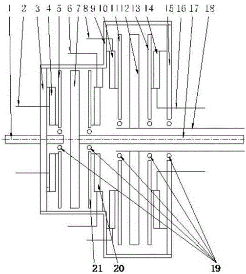
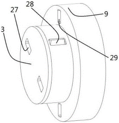
[0023] The present invention provides a dual-output disk structure of a permanent magnet torque converter, the output shaft of the first output disk is connected to the odd-numbered gears of the transmission, and the output hollow shaft of the second output disk is connected to the even-numbered gears of the transmission, and there are three moving disks when shifting gears Participate in the transmission of power, thereby reducing the transmission torque of each moving disk, better introducing engine speed adjustment, making the shifting action easier to achieve, improving the working efficiency of the permanent magnet torque converter in the shifting transition mode, and improving the life of the equipment.

[0024]As an embodiment of the present invention, the present invention provides a double output disk structure of a permanent magnet torq...


PUM

PropertyMeasurementUnit
Angleaaaaaaaaaa

Abstract

The invention discloses a dual-output magnetic disk structure of a permanent-magnet torque converter. According to the dual-output magnetic disk structure, an input shaft penetrates through a magnetic disk frame first disk, the magnetic disk frame first disk is arranged on one side of a magnetic disk frame outer barrel, a magnetic disk frame second disk is arranged on the other side of the magnetic disk frame outer barrel, the magnetic disk frame first disk is connected with a first movable magnetic disk, a first output magnetic disk is connected with a first output magnetic disk output shaft, the outer side of the front end of the first output magnetic disk output shaft is sleeved by a second movable magnetic disk, the second movable magnetic disk is connected with an inner wall of the magnetic disk frame outer barrel, the outer side of the rear end of the first output magnetic disk output shaft is sleeved by a second output magnetic disk output hollow shaft, the outer side of the front end of the second output magnetic disk output hollow shaft is sleeved by a second output magnetic disk, a third movable magnetic disk is arranged on the front side of the second output magnetic disk, a fourth movable magnetic disk is arranged on the rear side of the second output magnetic disk, the third movable magnetic disk is connected with the inner wall of the magnetic disk frame outer barrel, and the fourth movable magnetic disk is connected with the magnetic disk frame second disk. The dual-output magnetic disk structure disclosed by the invention enables gear shifting action to be easy to achieve, improves work efficiency of a gear shifting transition work condition of the permanent-magnet torque converter and prolongs equipment service life.

Description

technical field [0001] The invention relates to the field of supporting equipment of a permanent magnet torque converter, in particular to a double output disk structure of a permanent magnet torque converter. It is suitable for general machinery, household appliances, robots, automobiles, rail vehicles, ships and aircraft, especially for vehicles. Background technique [0002] The permanent magnet torque converter has two working modes, one is that the disk frame and the output disk rotate at the same speed, the left and right moving disks drive the output disk synchronously, and the output torque is the sum of the magnetic torque applied to the driving disk on the left and right sides, and it works at point a and At a certain point between point b, stable torque is output; another working mode is that the rotation speed of the disk shelf and the output disk are different, and the disk shelf then transmits the power gap to the moving disk. At this time, the phase difference...

Claims


Application Information

Patent Timeline
IPC IPC(8): H02K49/10
CPCH02K49/108
Inventor 邹政耀王章逸
Owner JINLING INST OF TECH
Learn More