New-type composite loudspeaker diaphragm

A loudspeaker and composite technology, which is applied in the field of new composite speaker diaphragms, can solve the problems of insufficient support, insufficient sound quality, unfavorable miniaturization, etc., and achieve the effect of improving structural support and sound quality performance

Pending Publication Date: 2017-06-13
苏州长阳电子科技有限公司
View PDF0 Cites 0 Cited by
  • Summary
  • Abstract
  • Description
  • Claims
  • Application Information

AI Technical Summary

Problems solved by technology

[0008] In view of the above-mentioned defects and problems of the traditional loudspeaker structure in the prior art, such as insufficient supporting force, insufficient sound quality, and unfavorable miniaturization, the purpose of the embodiment of the present invention is to provide a new type of composite speaker diaphragm, speaker monomer and speaker system or Electronic equipment, improve the damping characteristics of the dynamic speaker vibration system and effectively enhance the structural support of the vibration system, especially the vertical structural support, effectively suppress the nonlinear motion of the voice coil and significantly improve the power bearing

Method used


Image

  • New-type composite loudspeaker diaphragm
  • New-type composite loudspeaker diaphragm
  • New-type composite loudspeaker diaphragm

Examples


Embodiment 1

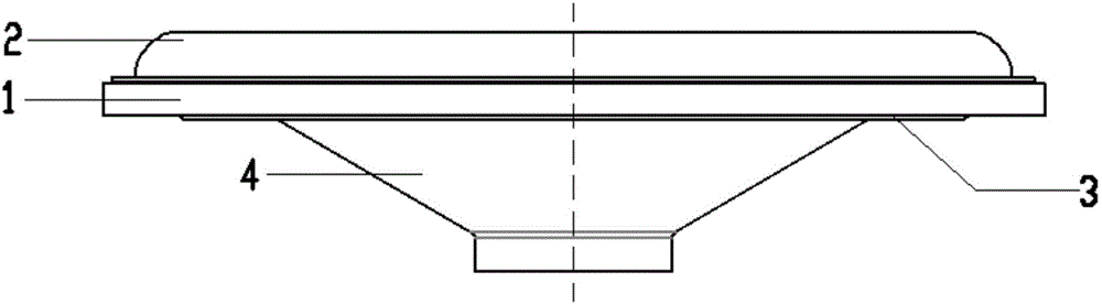
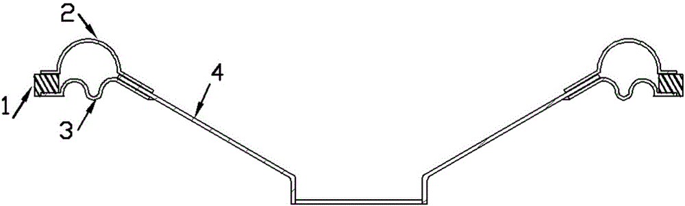
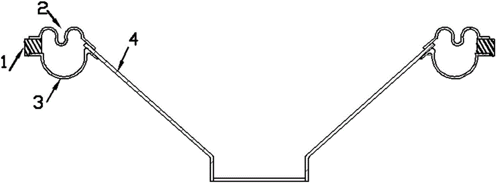
[0044] Such as Figure 1-6 As shown in , the diaphragm body 4 is an inverted cone; the bonding and combination process of its assembly is as follows: respectively use the preferred customized mold to respectively connect the upper ring 2 with the inverted cone diaphragm body 4 and the lower ring 3 Carry out positioning bonding with the sealing gasket 1 made of plastic material, and then put the semi-finished product of the upper ring 2 and the inverted cone diaphragm body 4, the semi-finished product of the lower ring 3 and the sealing gasket 1 into the customized mold to complete the positioning and Final gluing is done.

[0045] In this process, customized molds can also be used to respectively position and bond the upper ring 2 and the sealing gasket 1, the lower ring 3 and the inverted cone diaphragm body 4, and then the semi-finished products of the upper ring 2 and the sealing gasket 1 , The semi-finished products of the lower ring 3 and the inverted conical diaphragm b...

Embodiment 2

[0048] Such as Figure 7-9 As shown in , the diaphragm body 4 is a raised spherical arcuate body; the bonding combination process of its assembly is: using a preferred customized mold to position and glue the integrally formed upper and lower rings and the spherical diaphragm body 4 Then put them together with the plastic sealing gasket 1 into a customized mold to complete the positioning and bonding; this process can also use a customized mold to position and bond the integrally formed upper and lower rings and the sealing gasket 1, and then with The spherical diaphragm body 4 is placed together into a customized mold to complete positioning bonding.

[0049] In this embodiment, when the upper ring 2 is an upwardly convex hemispherical arc, the optional shape of the matched lower ring 3 is: an upwardly convex hemispherical arc, a downwardly concave hemispherical Arc shape; when the upper ring 2 is a downwardly recessed hemispherical arc, the matched lower ring 3 is a downwar...

Embodiment 3

[0051] Such as Figure 10-12 As shown in , the diaphragm body 4 is a circular plane.

[0052] In this embodiment, when the upper ring 2 is an upwardly convex hemispherical arc, the optional shape of the matched lower ring 3 is: an upwardly convex hemispherical arc, a downwardly concave hemispherical Arc shape; when the upper ring 2 is a downwardly recessed hemispherical arc, the matched lower ring 3 is a downwardly recessed hemispherical arc.


PUM


Abstract

The invention discloses a novel composite loudspeaker diaphragm, which is composed of an upper ring, a lower ring, a sealing gasket and a diaphragm body, the lower ring is located at the lower part of the upper ring, and the outer edges of the upper and lower rings are sandwiched by The sealing gasket makes the upper and lower rings merge and seal to form an air cushion with a closed cavity structure with a certain height and width. The inner edge of the upper and lower rings is inserted or installed with a diaphragm body; the diaphragm body is inverted The cone, raised spherical arcuate body or circular plane, and the outer surface is covered with a damping layer, while inheriting the advantages of the existing rings, it significantly improves the structural support of the vibration system of various types of speaker units and the resulting At the same time, it reduces the various types of split vibration of the diaphragm and improves the sound quality performance. In addition, due to the integrated molding, it is conducive to the realization of thinning of the speaker diaphragm, speaker unit, speaker system and electronic equipment, and more Energy saving and environmental protection.

Description

technical field [0001] The invention belongs to the technical field of audio equipment, and in particular relates to a novel composite loudspeaker diaphragm. Background technique [0002] In the current prior art, the speaker unit is an electro-acoustic energy conversion device that drives the diaphragm to vibrate through an electric signal, and the diaphragm vibrates to drive air to produce sound. Generally, it consists of three parts: magnetic conduction system, support system and vibration system. In terms of the vibration system of a moving coil speaker, it is generally composed of a diaphragm, a centering support, a voice coil and a dust cover, and the diaphragm is composed of a cone and a ring. The voice coil is fixed by the cone of the diaphragm and the spacer and is placed in the middle of the magnetic gap of the magnetic circuit system. When working, the voice coil receiving the electrical signal is subjected to magnetic force and drives the diaphragm to reciproca...

Claims


Application Information

Patent Timeline
Patent Type & Authority Applications(China)
IPC IPC(8): H04R7/12
CPCH04R7/12
Inventor 姜维波
Owner 苏州长阳电子科技有限公司
Why Eureka
Try Eureka