
Detection apparatus used for light source driving circuit

A light source driving circuit and detection device technology, which is applied in the direction of electric lamp circuit layout, light source, electric light source, etc., can solve the problems of limited test range and inability to apply circuit board screening, etc., to reduce human operation, improve detection intelligence, and improve efficiency Effect

Inactive Publication Date: 2017-06-13
BEIJING INST OF COMP TECH & APPL
View PDF6 Cites 0 Cited by
  • Summary
  • Abstract
  • Description
  • Claims
  • Application Information

AI Technical Summary

Problems solved by technology

[0002] The existing light source driving circuit test method is mechanical and simple in principle, but it takes time to build the test, purely manual and manual detection of the function of the circuit board is normal, and only use resistors to simulate the real load (light source), the test range is limited, and cannot Ideal for high-volume board screening

Method used


Image

  • Detection apparatus used for light source driving circuit
  • Detection apparatus used for light source driving circuit

Examples


Embodiment Construction

[0014] In order to make the purpose, content, and advantages of the present invention clearer, the specific implementation manners of the present invention will be further described in detail below in conjunction with the accompanying drawings and embodiments.

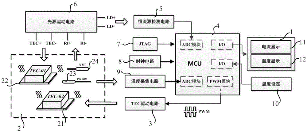
[0015] figure 1 Shown is the circuit module diagram of the detection device of the light source driving circuit, as figure 1 As shown, the detection device of the light source driving circuit includes: a constant current source detection circuit 5 , a temperature adjustment module 2 , and a temperature control module 4 .

[0016] refer to figure 1 , the constant current source detection circuit 5 is used to detect the output current of the light source drive circuit 6; the temperature regulation module 2 is used to adjust the current according to the temperature of the light source drive circuit 6, to adjust the temperature value of the temperature regulation module 2, and to the light source The drive circuit 6 prov...


PUM


Abstract

The invention discloses a detection apparatus used for a light source driving circuit. The detection apparatus comprises a current detection module, a temperature adjustment module, and a temperature control module, wherein the current detection module is used for detecting the output current of the light source driving circuit; the temperature adjustment module is used for adjusting current according to the temperature of the light source driving circuit, adjusting the temperature value of the temperature adjustment module and supplying the adjusted temperature value for the light source driving circuit; and the temperature control module is used for adjusting the temperature value of the temperature adjustment module. The detection apparatus used for the light source driving circuit disclosed by the invention is applied to a screening test of the light source driving circuit, and solves the problems of time consumption, low coverage performance and the like of the existing testing method; and in addition, the detection apparatus is of practical meaning to improvement of light source driving circuit detecting and screening efficiency, reduction of manual operation and improvement of detection intelligence.

Description

technical field [0001] The purpose of the present invention is to design an automatic and integrated detection device for the light source drive circuit, which is applied to the screening test of the light source drive circuit, and solves the problems of time-consuming and poor coverage of the current test method. It has practical significance for improving the efficiency of the detection and screening light source drive circuit, reducing human operation, and improving detection intelligence. Background technique [0002] The existing light source driving circuit test method is mechanical and simple in principle, but it takes time to build the test, purely manual and manual detection of the function of the circuit board is normal, and only use resistors to simulate the real load (light source), the test range is limited, and cannot Suitable for high-volume circuit board screening. Contents of the invention [0003] The object of the present invention is to provide a detec...

Claims


Application Information

Patent Timeline
IPC IPC(8): H05B37/02
Inventor 杨慧李敏郭建华
Owner BEIJING INST OF COMP TECH & APPL
Learn More