
Staggered and stacked transfer box

A turnover box and stacking technology, which is applied in the field of dislocation stacking turnover boxes, can solve the problems of easy crushing, poor load-bearing capacity and poor pressure-bearing capacity of the turnover box, and achieves strong anti-dumping ability, improved folding efficiency, The effect of improving performance and support

Active Publication Date: 2017-06-16
浙江正基塑业股份有限公司
View PDF4 Cites 6 Cited by
  • Summary
  • Abstract
  • Description
  • Claims
  • Application Information

AI Technical Summary

Problems solved by technology

However, during the stacking process, the upper turnover box and the goods inside are all under pressure on the side plate of the lower turnover box. When the lowermost turnover box is placed on the ground, due to the formation of a rib in the side plate or A concave step is formed at the bottom, so the bottom of the side plate cannot bear the load, which will cause the lowermost turnover box to have poor load-bearing capacity and be easily crushed
[0003] As an existing technology, the patent number is: 201220285604.1, and the patent name is: Turnover box. Although this utility model patent can realize the function of misplaced stacking, it also has shortcomings such as poor pressure bearing capacity.

Method used


Image

  • Staggered and stacked transfer box
  • Staggered and stacked transfer box
  • Staggered and stacked transfer box

Examples


Embodiment 1

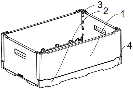
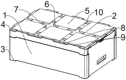
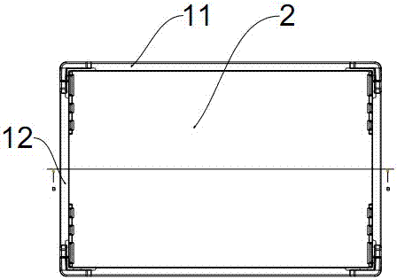
[0037] Such as figure 1 , figure 2 , image 3 , Figure 4 As shown, the turnover box described in this embodiment includes a base plate 2 and four side plates 1, the base plate 2 and the four side plates 1 form a semi-closed box, and the four sides at the upper end of the box The side plate 1 corresponding to the four corners is provided with an upward raised block 3, and the bottom plate 2 corresponding to the four corners of the lower end of the box is provided with an inner concave cavity 4 whose shape and size are consistent with the raised block 3. The cavity 4 and the protruding block 3 can be positioned in cooperation. The protruding block 3 is an L-shaped structure, and the corners of the protruding block 3 correspond to the corners of the upper end of the box body.

[0038] Six positioning protrusions 5 are arranged on the lower surface of the base plate 2, and a No. 1 groove 6 is formed between the positioning protrusions 5 in the length direction of the base p...

Embodiment 2

[0041] Such as figure 1 , figure 2 , image 3 , Figure 4 As shown, the turnover box described in this embodiment includes a base plate 2 and four side plates 1, the base plate 2 and the four side plates 1 form a semi-closed box, and the four sides at the upper end of the box The side plate 1 corresponding to the four corners is provided with an upward raised block 3, and the bottom plate 2 corresponding to the four corners of the lower end of the box is provided with an inner concave cavity 4 whose shape and size are consistent with the raised block 3. The cavity 4 and the protruding block 3 can be positioned in cooperation. The protruding block 3 is an L-shaped structure, and the corners of the protruding block 3 correspond to the corners of the upper end of the box body.

[0042] Six positioning protrusions 5 are arranged on the lower surface of the base plate 2, and a No. 1 groove 6 is formed between the positioning protrusions 5 in the length direction of the base p...


PUM


Abstract

The invention relates to the technical field of transfer boxes, in particular to a staggered and stacked transfer box. The staggered and stacked transfer box comprises a base plate and four side plates, wherein the base plate and the four side plates form a semi-closed box body, upward protrusion blocks are arranged on the side plates corresponding to four corners of the upper end of the box body, inner cavities consistent to the protrusion blocks in shape and size are formed in the baseplate corresponding to the four corners of the lower end of the box body, and the inner cavities are matched with the protrusion blocks for positioning. The staggered and stacked transfer box achieves matching in the stacking process through the design of the protrusion blocks and the inner cavities and has strong toppling prevention capability. In addition, supporting protrusions are arranged at the lower ends of the side plates, no gap exist below the side plates of each transfer box during weight bearing, and the usage performance and supporting capability of the transfer box are greatly improved.

Description

technical field [0001] The invention relates to the technical field of turnover boxes, in particular to a turnover box with misplaced stacking. Background technique [0002] In the prior art, in order to prevent the turnover box from toppling during the stacking process, an annular rib is provided at the bottom of the turnover box, or an annular concave is provided on the edge of the bottom to form a step, and the annular rib or step is connected with the lower turnover box The opening fits, so as to realize the function of anti-dumping. However, during the stacking process, the upper turnover box and the goods inside are all under pressure on the side plate of the lower turnover box. When the lowermost turnover box is placed on the ground, due to the formation of a rib in the side plate or A concave step is formed at the bottom, so the bottom of the side plate cannot bear the load, which will cause the lowermost turnover box to have poor load-bearing capacity and be easily...

Claims


Application Information

Patent Timeline
Patent Type & Authority Applications(China)
IPC IPC(8): B65D21/032
CPCB65D21/0212
Inventor 张震原商春杰徐晓明
Owner 浙江正基塑业股份有限公司
Learn More