Position-changing lamplight assembly

A lighting and component technology, which is applied to the parts of lighting devices, lighting devices, outdoor lighting, etc., can solve the problems of affecting the life of lamps, high power consumption, and high cost, so as to avoid the decline of lamp life, low power consumption, low cost effect

Inactive Publication Date: 2017-06-16
潼南县铭辉灯具制造厂
View PDF0 Cites 2 Cited by
  • Summary
  • Abstract
  • Description
  • Claims
  • Application Information

AI Technical Summary

Problems solved by technology

In some occasions where the lighting area needs to be continuously changed (such as a stage), only multiple lamps can be installed, and the lighting area can be changed by switching the lamps at different positions. Not only is the cost high, the power consumption is large, and the frequent switching of the lamps will greatly affect lamp life

Method used


Image

  • Position-changing lamplight assembly

Examples


Embodiment 1

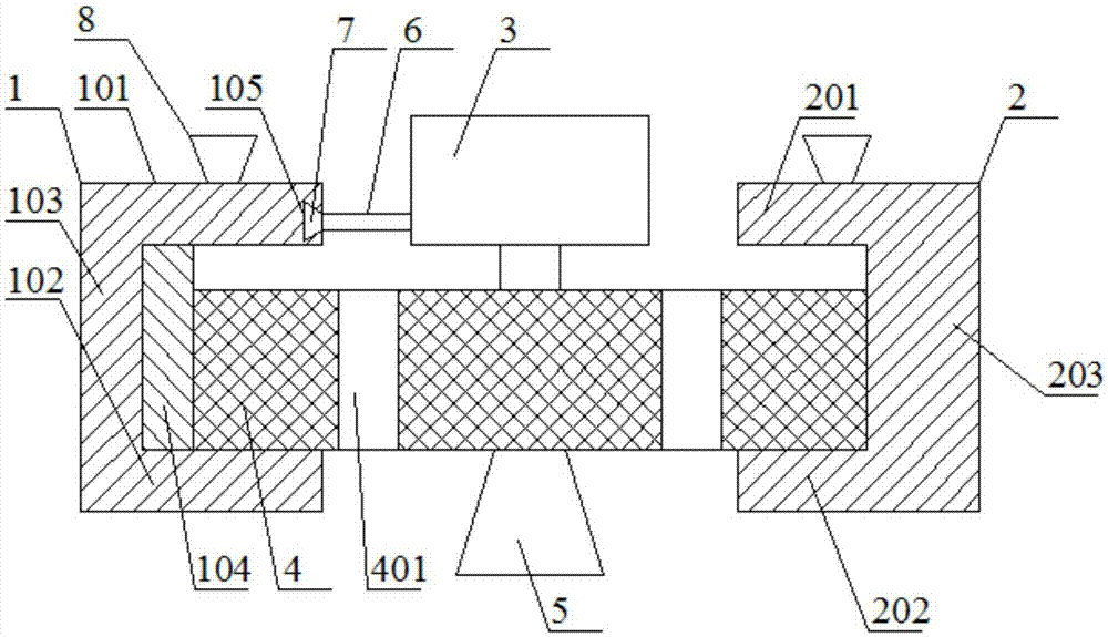
[0023] Such as figure 1 As shown, the displacement lighting assembly includes a driving track 1, a supporting track 2, a motor 3, a gear 4 and a lamp 5; the driving track 1 includes an upper horizontal section A101, a lower horizontal section A102 and a vertical section A103, and the upper horizontal section A101 is located at the lower Directly above the horizontal section A102, the upper and lower ends of the vertical section A103 are respectively connected to the ends of the upper horizontal section A101 and the lower horizontal section A102; the driving track 1 also includes a horizontal rack 104 fixed on the side of the vertical section A103, the horizontal rack 104 is located between the upper horizontal section A101 and the lower horizontal section A102; the support track 2 includes the upper horizontal section B201, the lower horizontal section B202 and the vertical section B203, the upper horizontal section B201 is located directly above the lower horizontal section B2...

Embodiment 2

[0027] Such as figure 1 As shown, on the basis of Embodiment 1, this embodiment also includes a connecting bar 6, one end of the connecting bar 6 is connected to the motor 3, and the other end of the connecting bar 6 is provided with a dovetail protrusion 7; the upper horizontal section A101 is provided with a dovetail chute 105 on the side close to the motor 3 , and the dovetail protrusion 7 cooperates with the dovetail chute 105 .

[0028] The motor 3 is slidably fixed on the upper horizontal section A101 through the cooperation of the dovetail chute 105 and the dovetail protrusion 7, and the motor 3 does not rotate and can move with the gear 4 in the horizontal direction during the working process.

Embodiment 3

[0030] Such as figure 1 As shown, this embodiment is based on Embodiment 1, and the gear 4 is provided with a plurality of lightening holes 401 .

[0031] The gear 4 is provided with a plurality of lightening holes 401, which reduces the weight of the present invention.


PUM


Abstract

The invention discloses a displacement lighting assembly, which includes a horizontal rack fixed on the side of a vertical section A, the horizontal rack is located between the upper horizontal section A and the lower horizontal section A; the driving track and the supporting track are arranged opposite to each other; Arrangement, the gear is set between the drive track and the support track, the gear is jointly supported by the lower horizontal section A and the lower horizontal section B, and the gear meshes with the horizontal rack; the motor is set above the gear, and the output shaft of the motor is connected to the center of the gear. The motor is fixed on the upper horizontal section A, and the motor can slide horizontally along the upper horizontal section A; the lamp is arranged on the lower surface of the gear; and the suction cups arranged on the upper surface of the upper horizontal section A and the upper horizontal section B are also included. The invention is easy to install, only needs one lamp to realize the transformation of the lighting area, has low cost and low power consumption, and avoids the reduction of lamp life caused by frequent switching of lamps.

Description

technical field [0001] The invention relates to a lamp. Background technique [0002] Most of the existing lamps are fixed installations, which can only illuminate fixed areas. In some occasions where the lighting area needs to be continuously changed (such as a stage), only multiple lamps can be installed, and the lighting area can be changed by switching the lamps at different positions. Not only is the cost high, the power consumption is large, and the frequent switching of the lamps will greatly affect lamp life. Contents of the invention [0003] The purpose of the present invention is to overcome the shortcomings of the prior art and provide a displacement light assembly. [0004] The object of the present invention is achieved through the following technical solutions: [0005] Displacement lighting components, including drive track, support track, motor, gear and lamp; drive track includes upper horizontal section A, lower horizontal section A and vertical secti...

Claims


Application Information

Patent Timeline
Patent Type & Authority Applications(China)
IPC IPC(8): F21V21/34F21W131/105F21W131/406
CPCF21V21/34F21W2131/105F21W2131/406
Inventor 孙楷
Owner 潼南县铭辉灯具制造厂
Why Eureka
Try Eureka