A kind of water treatment system and method

A technology for a water treatment system and treatment liquid, applied in the field of water treatment, can solve the problems of poor anti-fouling and blocking performance of reverse osmosis membranes, and achieve the effects of avoiding the reduction of the life of the membrane bag, reducing the driving pressure, and improving the anti-fouling blocking performance.

Active Publication Date: 2022-04-26
JIANGSU KUNYI ENVIRONMENTAL ENG CO LTD
View PDF6 Cites 0 Cited by
  • Summary
  • Abstract
  • Description
  • Claims
  • Application Information

AI Technical Summary

Problems solved by technology

[0007] In order to solve the problem of poor anti-fouling performance of the reverse osmosis membrane of the membrane module in the prior art, the present invention provides a treatment system and method to improve the anti-fouling performance of the reverse osmosis membrane of the membrane module

Method used


Image

  • A kind of water treatment system and method
  • A kind of water treatment system and method
  • A kind of water treatment system and method

Examples


Embodiment 1

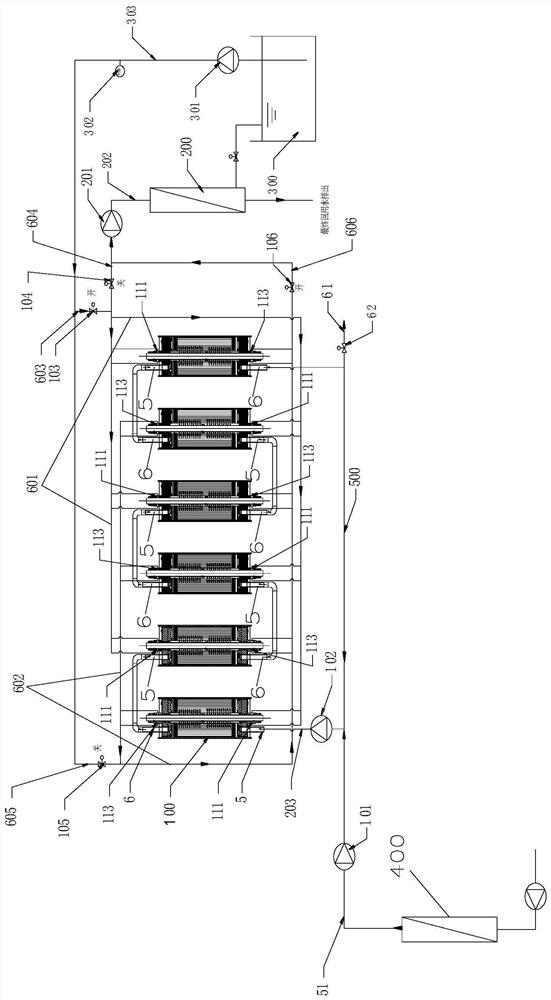
[0073] Such as Figure 1~2 , the first port 111 is located at the same end of the membrane shell 1 as the raw water interface 5 , and the second port 113 is located at the same end of the membrane shell 1 as the concentrated water interface 6 .

[0074] Working principle of switching mechanism:

[0075] Such as figure 1 , open the first valve 103 and the fourth valve 106, close the second valve 104 and the third valve 105, at this time, the first pipeline 601 inputs brine, and the second pipeline 602 outputs the mixed solution; at this time, the first port 111 enters brine, and the second Two ports 113 out of the mixed solution;

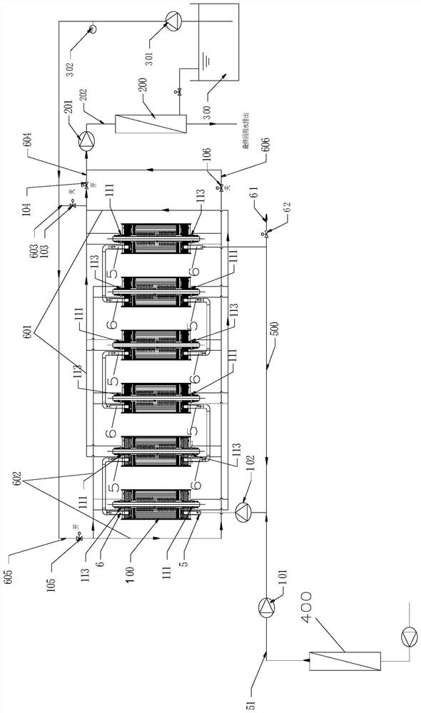
[0076] When switching is required, such as figure 2 , open the second valve 104 and the third valve 105, close the first valve 103 and the fourth valve 106, at this time, the second pipeline 602 inputs brine, the first pipeline 601 outputs the mixed solution, at this time, the second port 113 enters brine, the second One mouthful of 111 out of the...

Embodiment 2

[0078] Such as Figure 7-8 , the first port 111 is set at one end close to the first pipe 601 , and the second port 113 is set at one end close to the second pipe 603 .

[0079] Working principle of switching mechanism:

[0080] Such as Figure 7 , open the first valve 103 and the fourth valve 106, close the second valve 104 and the third valve 105, at this moment, the first pipeline 601 inputs brine, the second pipeline 602 outputs the mixed solution, at this time, the first port 111 enters brine, and the second Two ports 113 out of the mixed solution;

[0081] When switching is required, such as Figure 8 , open the second valve 104 and the third valve 105, close the first valve 103 and the fourth valve 106, at this time, the second pipeline 602 inputs brine, the first pipeline 601 outputs the mixed solution, at this time, the second port 113 enters brine, the second One mouthful of 111 out of the mixture.


PUM


Abstract

The invention belongs to the field of water treatment. A water treatment system comprises a liquid inlet pipe to be treated, a concentrated liquid outlet pipe and at least one circulation assembly. A return pipeline is connected between the liquid inlet pipe to be treated and the concentrated liquid outlet pipe. The circulation assembly includes a liquid inlet pipe and a liquid outlet pipe communicated with the return line, a membrane module is arranged between the liquid inlet pipe and the liquid outlet pipe, and the inner cavity of the water production pipe of the membrane module includes a brine channel and a Mixed solution channel, the two ends of the water production pipe are respectively provided with a first port and a second port, one of the first port and the second port is used to inject brine into the brine channel, and the other is used to export the mixed solution in the mixed solution channel, water The treatment system also includes a switching mechanism, which is used to switch the liquid flow direction between the first port and the second port. The invention increases the flow rate of the liquid, and the positions of the brine channel and the mixed liquid channel are switched to each other, which improves the anti-fouling and clogging of the membrane module. performance.

Description

technical field [0001] The invention belongs to the field of water treatment, in particular to a water treatment system and method. Background technique [0002] With the increasingly stringent environmental protection policies and the gradual enhancement of people's awareness of environmental protection, in recent years, many industries have required the resource utilization of wastewater, and the near-zero discharge of wastewater has also been put on the agenda. In the process of near-zero discharge and resource utilization of wastewater, reverse osmosis technology has been most widely and effectively applied. At present, in the field of reverse osmosis membrane application, roll membrane (RO) and disc tube membrane module (DTRO) and network tube type open channel membrane module (STRO) occupy the leading market. However, there are still some technical defects and deficiencies in the application of the above-mentioned membrane elements or components: [0003] 1. Regardle...

Claims


Application Information

Patent Timeline
Patent Type & Authority Patents(China)
IPC IPC(8): C02F1/44
CPCC02F1/44C02F1/441C02F1/442C02F2301/066C02F2301/046C02F2301/08C02F2303/14
Inventor 李方越谢军英
Owner JIANGSU KUNYI ENVIRONMENTAL ENG CO LTD
Why Eureka
Try Eureka