Shell assembly of range hood and range hood

A range hood and component technology, applied in the direction of removing oil fume, household stoves/stoves, heating methods, etc., can solve the problems of increasing the flow path of oil fume flowing into the fan, affecting the appearance of the hood, increasing the flow pressure loss, etc., so as to enhance the flue gas The effect of capturing ability, improving speech intelligibility, increasing air volume and pressure

Pending Publication Date: 2017-06-16
GUANGDONG MIDEA KITCHEN APPLIANCES MFG CO LTD +1
View PDF7 Cites 15 Cited by
  • Summary
  • Abstract
  • Description
  • Claims
  • Application Information

AI Technical Summary

Problems solved by technology

This structure will greatly affect the distribution of the negative pressure area of ​​the main main air inlet, and then affect the effect of the main main air inlet on absorbing oil fume
On the other hand, the air intake from the lower side increases the flow path of the oil fume into the fan, which in turn increases the loss of the flow head
[0004] The lower main air inlet greatly affects the distribution of the negative pressure area of ​​the main main air inlet, which in turn affects the oil fume suction effect of the main main air inlet
Moreover, the air intake from the lower side increases the flow path of the oil fume into the fan, which in turn increases the flow pressure loss
On the other hand, for domestic hood users, there are basically two cookers and stoves under each range hood, and the lower side air intake scheme cannot well meet the needs of users
More importantly, the opening on the lower side will affect the appearance of the hood, and it is easy to cause oil dripping and oil leakage
In consideration of manufacturability, its complex structure, high cost, and complicated actual installation process are not conducive to mass production

Method used


Image

  • Shell assembly of range hood and range hood
  • Shell assembly of range hood and range hood
  • Shell assembly of range hood and range hood

Examples


Embodiment Construction

[0043] Embodiments of the invention are described in detail below, examples of which are illustrated in the accompanying drawings. The embodiments described below by referring to the figures are exemplary and are intended to explain the present invention and should not be construed as limiting the present invention.

[0044] In describing the present invention, it should be understood that the terms "center", "longitudinal", "transverse", "length", "width", "thickness", "upper", "lower", "front", " Rear", "Left", "Right", "Vertical", "Horizontal", "Top", "Bottom", "Inner", "Outer", "Axial", "Radial", "Circumferential" The orientation or positional relationship indicated by etc. is based on the orientation or positional relationship shown in the drawings, and is only for the convenience of describing the present invention and simplifying the description, rather than indicating or implying that the referred device or element must have a specific orientation, use a specific Azim...


PUM


Abstract

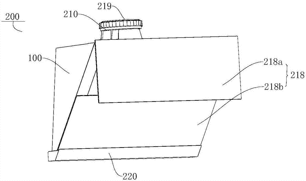
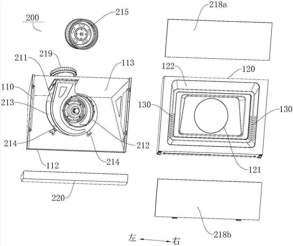
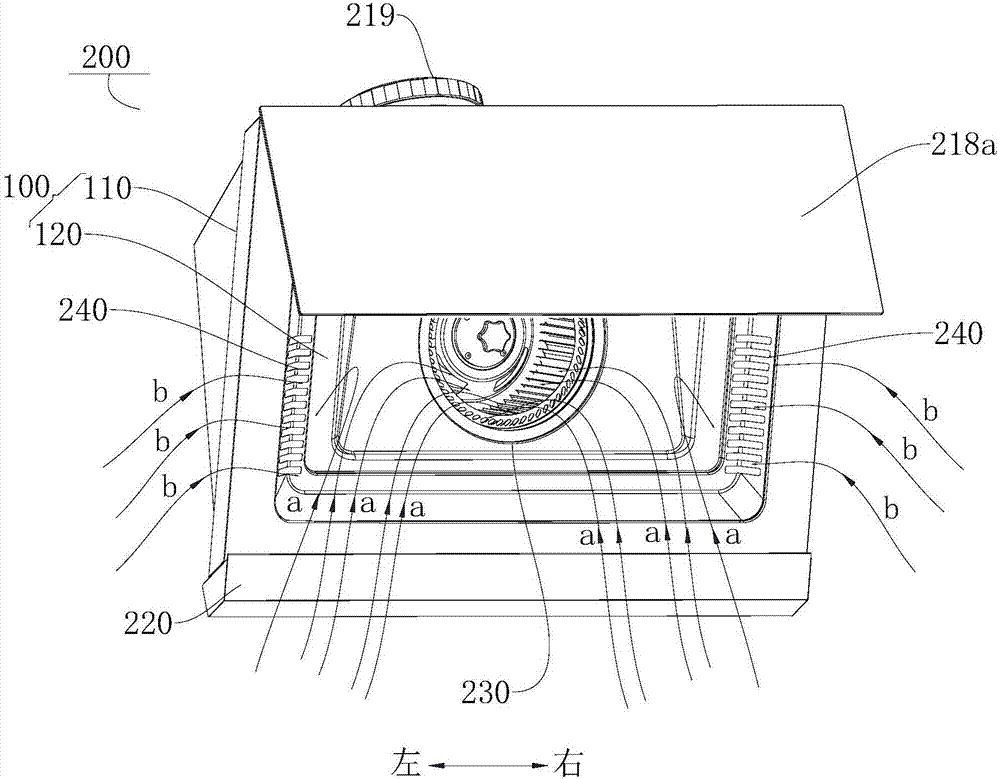
The invention discloses a shell assembly of a range hood and the range hood. The range hood comprises a shell, a partition and a fan assembly, wherein an opening is formed in the front side of the shell; the partition is arranged in the shell, and divides the inside of the shell into a front side cavity and a rear side cavity which are arrayed in the front-to-back direction; a main air inlet is formed in the partition; at least one of the partition and the shell defines an auxiliary air inlet; the auxiliary air inlet is close to the edge of the partition; the air feeding end opening of the fan assembly is formed at the main air inlet and is communicated with the front side cavity; an auxiliary air opening is formed in the fan assembly; the main air inlet and the air feeding end opening define a main air duct; the auxiliary air opening and the auxiliary air inlet define an auxiliary air duct. According to the range hood disclosed by the invention, the shell assembly and the fan assembly are used for defining the main air duct and the auxiliary air duct, so that the lampblack catching capacity of the range hood can be improved, the air feeding efficiency is improved, and the air volume and the air pressure are increased; therefore, the lampblack absorption effect of the range hood can be enhanced.

Description

technical field [0001] The present invention relates to the technical field of kitchen electrical equipment, in particular, to a shell assembly of a range hood and the range hood. Background technique [0002] With the improvement of people's health awareness, the range hood has gradually become an indispensable electrical appliance in every family. At present, the large air volume and suction power recognized by consumers has become the main selling point of the market, but the hood itself has the contradiction that the greater the air volume, the greater the noise. There are more and more complaints about noise in the market, and the industry has been looking for new noise reduction solutions. However, considering the system and structure of the range hood itself, it is very difficult to maintain low noise while maintaining a large air volume and high static pressure. things. The fan system is the core power system of the range hood, and the commonly used fan system is a...

Claims


Application Information

Patent Timeline
Patent Type & Authority Applications(China)
IPC IPC(8): F24C15/20
CPCF24C15/20
Inventor 闫亮何新奎魏喜明蒋济武靳思宇程杰锋王跃
Owner GUANGDONG MIDEA KITCHEN APPLIANCES MFG CO LTD
Why Eureka
Try Eureka