Laser cladding device with adjustable cladding track and method for adjusting cladding track width

A laser cladding and cladding technology, which is applied in laser welding equipment, metal processing equipment, welding equipment, etc., can solve the problems of unstable cladding track height, section shape, unfavorable cladding head arrangement of heat dissipation devices, etc., to solve the problem of laser cladding Limited power, guaranteed cladding effect, and improved cladding quality

Active Publication Date: 2018-11-13
ZHEJIANG UNIV OF TECH
View PDF6 Cites 1 Cited by
  • Summary
  • Abstract
  • Description
  • Claims
  • Application Information

AI Technical Summary

Problems solved by technology

[0004] Although the above method of the Fraunhofer Laser Institute in Germany can change the width of the cladding track by changing the spot size at different positions on the track, it does not adjust the powder delivery volume and The location of the powder delivery, which will cause fluctuations in the height of the cladding track and instability of the cross-sectional shape; in addition, because the high-power laser beam passing through the lens will cause heat accumulation on the lens, this solution uses a servo motor to drive the lens to move. Facilitates the placement of heat sinks in a small space inside the cladding head, thus limiting the power of the laser beam passing through the lens

Method used


Image

  • Laser cladding device with adjustable cladding track and method for adjusting cladding track width
  • Laser cladding device with adjustable cladding track and method for adjusting cladding track width
  • Laser cladding device with adjustable cladding track and method for adjusting cladding track width

Examples


Embodiment Construction

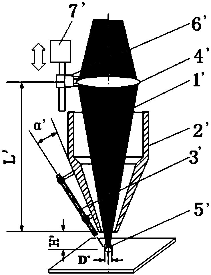
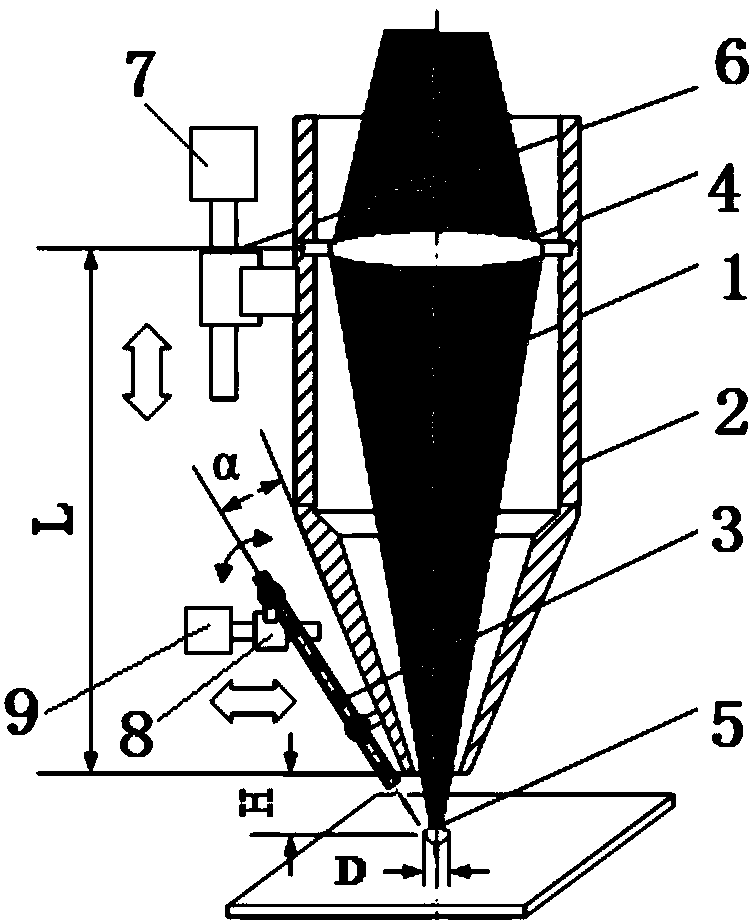
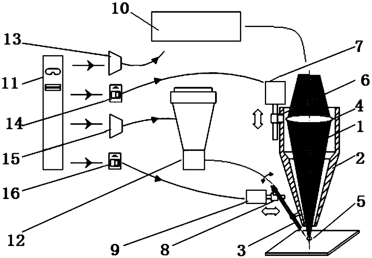
[0030] Referring to the accompanying drawings, the laser cladding device with adjustable cladding trajectory includes a laser cladding head component, a laser 10, a powder feeder 12 and a central controller 11, and both the laser 10 and the powder feeder 12 are connected to the laser cladding head component , the laser cladding head component, the laser 10 and the powder feeder 12 are all connected to the central controller 11;

[0031] The laser cladding head component includes a cladding head 2, the cladding head 2 is installed on a vertical adjustment device that can drive the cladding head 2 to move up and down in the vertical direction, and the cladding head 2 moves vertically A laser inlet is provided above the cladding head, and a laser outlet is provided below the cladding head 2 along the vertical direction; a lens 4 is provided in the cladding head 2, and the lens 4 is coaxially arranged with the cladding head 2;

[0032] The cladding head 2 is provided with a powder...


PUM


Abstract

The invention discloses a laser cladding device with an adjustable cladding track and a method for adjusting the width of the cladding track. The laser cladding device comprises a laser cladding head component, a laser, a powder feeder and a central controller, wherein the cladding head is mounted on a vertical adjusting device which can drive the cladding head to move up and down in the vertical direction; a lens is arranged in the cladding head; a powder feeding pipe is mounted on the cladding head through an angle adjusting device which can adjust the included angle between the powder feeding pipe and the cladding head; and a signal transformer, a powder feeding controller and a counter are arranged in the central controller. According to the laser cladding device, the width of the cladding track can be adjusted, the powder conveying quantity and powder feeding angle can be adjusted according to the change of the cladding width while the light spot size changes, fluctuation of height and instability of the section shape of the cladding track are avoided, the laser power density remains unchanged, the thickness of a cladding layer remains unchanged, and the cladding effect is guaranteed.

Description

technical field [0001] The invention relates to a laser cladding device with adjustable cladding track and a method for adjusting the width of the cladding track. Background technique [0002] The coaxial cladding head is a commonly used laser cladding processing tool. The structure of the traditional coaxial cladding head is: the fixed lens group passing through the central axis converges the laser beam, and the powder feeding flow symmetrically distributed along the same central axis The laser beam and the powder flow are converged on the same axis. The laser converging point and the powder converging point of this traditional coaxial cladding head are fixed, therefore, the adjustment and change of the section width at different positions cannot be realized on one cladding track. [0003] Thin-walled complex parts such as blades have the characteristics of thin walls, complex cross-sectional tracks, and cross-sectional widths that vary with the track. When using tradition...

Claims


Application Information

Patent Timeline
Patent Type & Authority Patents(China)
IPC IPC(8): B23K26/342B23K26/06
CPCB23K26/06B23K26/342
Inventor 姚建华胡晓冬陈智君骆芳张群莉王梁董刚吴国龙杨高林李波黄利安科瓦连柯·弗拉季米尔
Owner ZHEJIANG UNIV OF TECH
Why Eureka
Try Eureka