Gear transmission structure

A gear transmission, sliding plate technology, applied in metal processing and other directions, can solve the problems of weak bonding, offset saw table, heavy weight, etc., to avoid dimensional errors of materials, improve product qualification rate, and long service life. Effect

Inactive Publication Date: 2017-06-20
重庆智成友和会计服务有限公司
View PDF0 Cites 1 Cited by
  • Summary
  • Abstract
  • Description
  • Claims
  • Application Information

AI Technical Summary

Problems solved by technology

[0002] The existing processing saw machine includes a main frame and a track, and a saw table is set at both ends of the track. Due to the large number of parts and heavy weight of the saw table, the transmission gear and the row of gears rotate after a long period of use. There will be gaps between them due to wear, which will cause the combination between the transmission gear and the row of teeth to be weak and cause shaking, which will cause the saw table to shift back and forth, affecting the accuracy of processing
On the other hand, due to the different frequency of use of the teeth, different wear conditions will occur in different positions, so the operator cannot perform manual correction based on experience, resulting in dimensional errors of the material.

Method used


Image

  • Gear transmission structure
  • Gear transmission structure
  • Gear transmission structure

Examples


Embodiment Construction

[0017] Below in conjunction with accompanying drawing and embodiment

[0018] The present invention is described further:

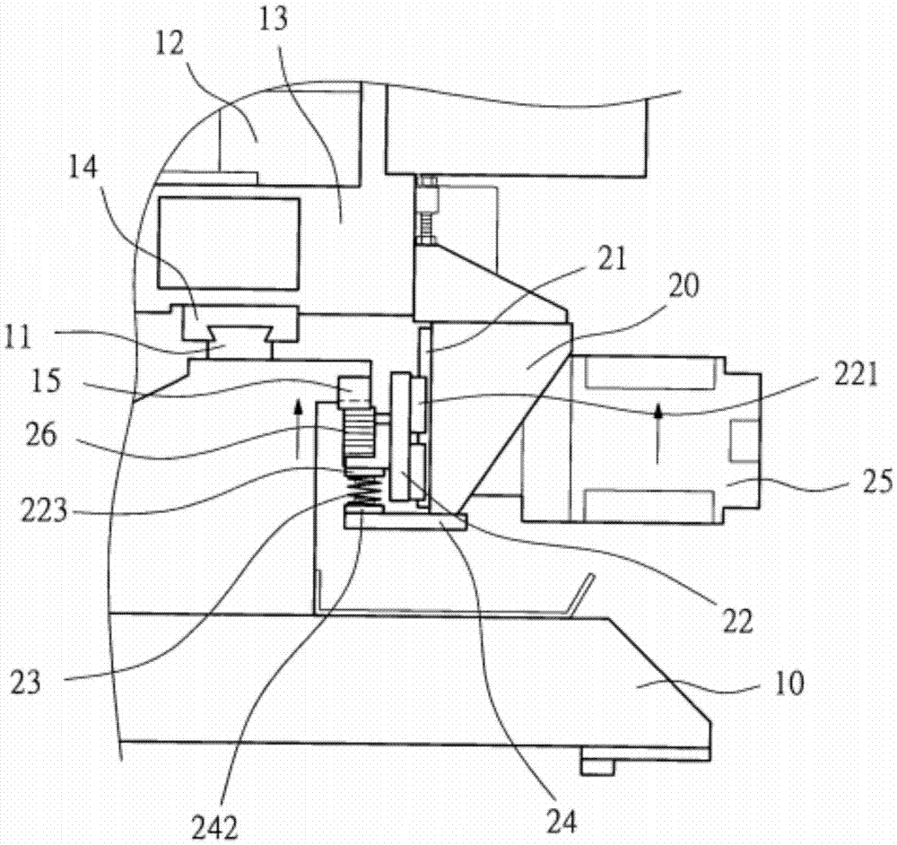
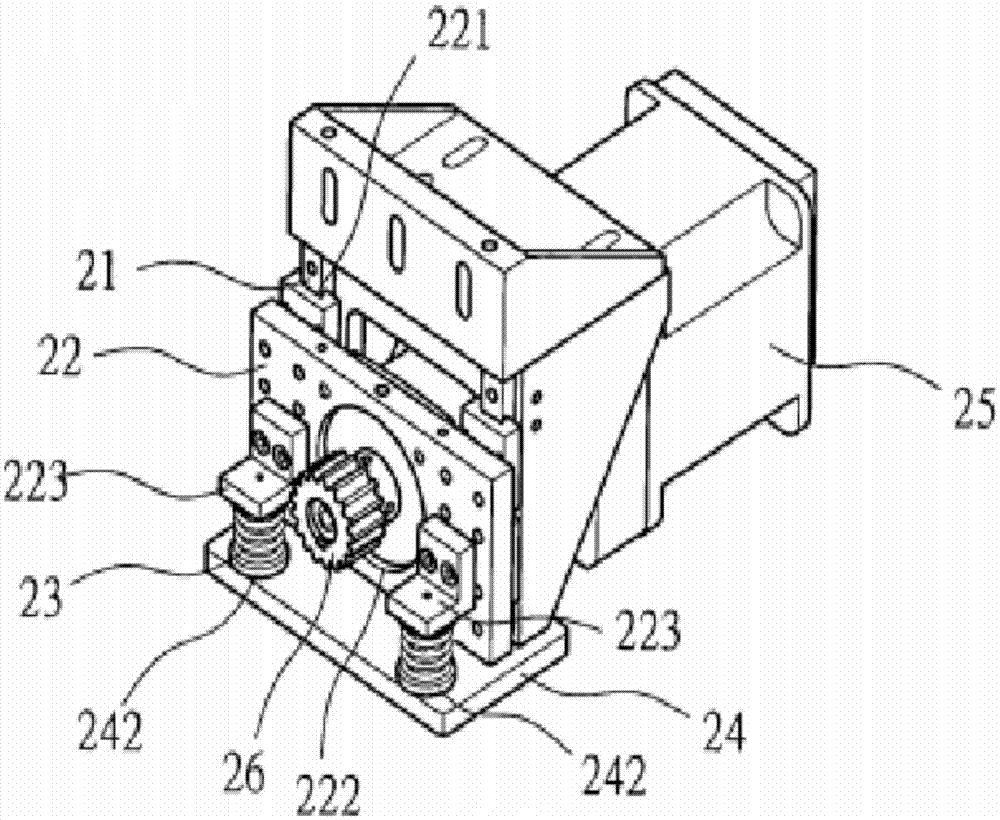
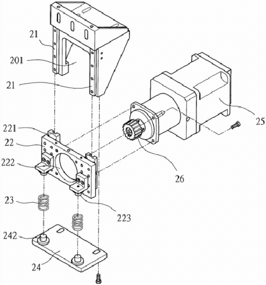
[0019] Such as Figure 1-Figure 4 As shown, a gear transmission structure includes a main frame 10, the main frame 10 is provided with a base plate 24, and the base plate 24 is provided with two first protrusions 242 and two limiting holes;

[0020] The bottom plate 24 is provided with a sliding plate 22, and one end surface of the sliding plate 22 is provided with two fitting grooves 221, and the middle part of the sliding plate 22 is provided with a through hole 222, and the radius of the through hole 222 is 10 cm; Between the grooves 221, the other end surface of the sliding plate 22 is provided with two second protrusions 223; the two first protrusions 242 are respectively connected to the two second protrusions 223 by springs 23;

[0021] The side of base 13 is provided with support seat 20, and support seat 20 extends downwards, and support seat 2...


PUM


Abstract

The invention discloses a gear transmission structure, comprising a main frame, a bottom plate is arranged on the main frame, two first protrusions and two limit holes are arranged on the bottom plate; a sliding plate is arranged on the bottom plate , one end surface of the sliding plate is provided with two fitting grooves, the middle part of the sliding plate is provided with a through hole, the radius of the through hole is 10cm; the through hole is located between the two fitting grooves, The other end surface of the sliding plate is provided with two second protrusions; the two first protrusions are respectively connected with the two second protrusions through springs. The invention eliminates the gap between the transmission gear and the row of teeth, and effectively avoids the dimensional error of the material. The utility model has the beneficial effects of low transformation cost, long service life, improved product qualification rate and the like.

Description

technical field [0001] The invention relates to a transmission device, in particular to a transmission gear structure. Background technique [0002] The existing processing saw machine includes a main frame and a track, and a saw table is set at both ends of the track. Due to the large number of parts and heavy weight of the saw table, the transmission gear and the row of gears rotate after a long period of use. There will be a gap between them due to wear, which will cause the combination between the transmission gear and the row of teeth to be weak and cause shaking, which will cause the saw table to shift back and forth, affecting the processing accuracy. On the other hand, due to the different frequency of use of the tooth row, different wear conditions will occur in different positions, so the operator cannot perform manual correction based on experience, resulting in dimensional errors of the material. [0003] Therefore, those skilled in the art are committed to deve...

Claims


Application Information

Patent Timeline
Patent Type & Authority Applications(China)
IPC IPC(8): B23Q5/56
CPCB23Q5/56
Inventor 邓静敏
Owner 重庆智成友和会计服务有限公司
Why Eureka
Try Eureka