Clamp for mounting magnet

A technology for mounting magnets and fixtures, applied in the field of magnet mounting fixtures, can solve the problems of time-consuming and laborious installation, inability to meet production needs, and low efficiency.

Active Publication Date: 2017-06-20
SUZHOU INDAL PARK ELION TECH
View PDF10 Cites 8 Cited by
  • Summary
  • Abstract
  • Description
  • Claims
  • Application Information

AI Technical Summary

Problems solved by technology

[0002] When assembling the rotor of a motor or an electric motor, it is necessary to install the magnetic tiles into the built-in installation groove of the rotor. In the prior art, the magnetic tiles are inserted into the built-in

Method used


Image

  • Clamp for mounting magnet
  • Clamp for mounting magnet
  • Clamp for mounting magnet

Examples


Embodiment Construction

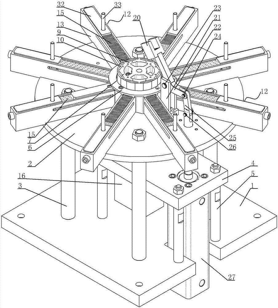
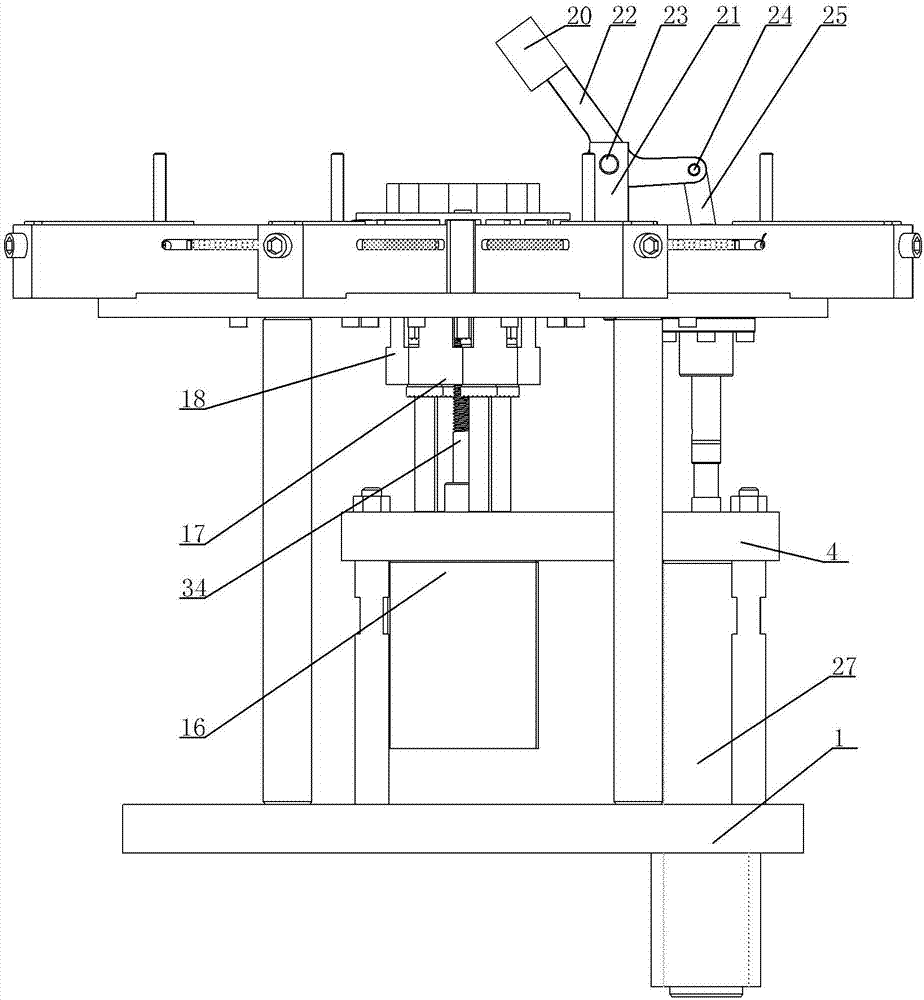
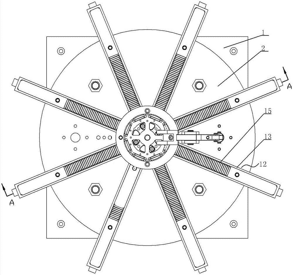
[0018] A kind of magnetic fixture, see Figure 1 ~ Figure 4 : It includes a base plate 1, an upper plate 2 is arranged directly above the base plate 1, the upper plate is supported on the base plate 1 through a plurality of first columns 3, and is arranged parallel to the base plate 2, and an installation is arranged between the base plate 1 and the upper plate 2. The plate 4 and the mounting plate 4 are supported on the bottom plate 1 through a number of second columns 5, and the center position of the upper plate 2 is provided with an upward convex structure 6, and the outer ring part of the upward convex structure 6 is fastened to the center position of the upper end surface of the bottom plate 1 by screws , the center position of the bottom plate 1 is the center hole, the center of the raised structure 6 is the positioning cavity 7, the rotor positioning fixture 8 is arranged in the installation cavity 7, the bottom of the rotor 9 is positioned on the rotor positioning fixt...


PUM


Abstract

The invention provides a clamp for mounting a magnet. Through the clamp for mounting the magnet, a magnetic shoe can be quickly assembled into a rotor, so that the mounting efficiency is ensured. The clamp for mounting the magnet comprises a base plate; an upper plate is arranged right above the base plate; the upper plate is supported on the base plate through a plurality of first upright posts, and the upper plate is arranged in parallel with the base plate; a mounting plate is arranged between the base plate and the upper plate; the mounting plate is supported on the base plate through a plurality of second upright posts; a central hole is formed in the central position of the base plate; an upper convex structure is arranged at the central position of the upper plate; a positioning cavity is formed in the centre of the upper convex structure; a rotor positioning clamp is arranged in the positioning cavity; the bottom of the rotor is positioned at the rotor positioning clamp; an outer ring through groove is formed in the position, corresponding to a radial angle direction of each built-in mounting groove of the rotor, of the outer ring surface of the lower end of the upper convex structure; a plurality of magnetic shoe mounting grooves which are in radial arrangement are annularly formed in the upper end surface of the upper plate.

Description

technical field [0001] The invention relates to the technical field of motor assembly, in particular to a clamp for installing magnets. Background technique [0002] When assembling the rotor of a motor or an electric motor, it is necessary to install the magnetic tiles into the built-in installation groove of the rotor. In the prior art, the magnetic tiles are inserted into the built-in groove of the ring cloth one by one by placing the rotor on a rotatable frame. In the installation groove, its installation is time-consuming and laborious, and the efficiency is low, which cannot meet the needs of production. Contents of the invention [0003] In view of the above problems, the present invention provides a fixture for installing magnets, which can quickly assemble the magnetic tiles into the rotor, ensuring installation efficiency. [0004] A fixture for installing magnets, characterized in that it includes a bottom plate, an upper plate is arranged directly above the bo...

Claims


Application Information

Patent Timeline
IPC IPC(8): B25B11/02H02K15/03
CPCB25B11/02H02K15/03
Inventor 赵猛涛
Owner SUZHOU INDAL PARK ELION TECH
Why Eureka
Try Eureka