Plug valve

A plug valve and valve core technology, applied in the field of plug valves, can solve problems such as inconvenient use and achieve the effect of convenient adjustment

Active Publication Date: 2017-06-20
ZHEJIANG XINTAO ELECTRONICS MACHINERY
View PDF8 Cites 9 Cited by
  • Summary
  • Abstract
  • Description
  • Claims
  • Application Information

AI Technical Summary

Problems solved by technology

However, traditional gas stoves mostly use traditional plunger valves to adjust the firepower. Often, the firepower does not change much after the knob is turned for a long time, and it will suddenly change a lot

Method used


Image

  • Plug valve
  • Plug valve
  • Plug valve

Examples


Embodiment 1

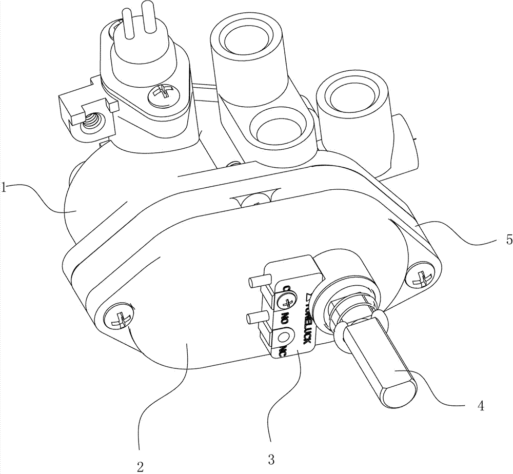
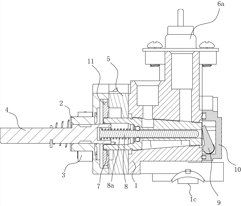
[0028] Figure 1 to Figure 9A plug valve is shown, which includes a valve body 1, on which a spool accommodating cavity is arranged, and a spool 7 is arranged in the spool accommodating cavity, and the two are connected in a rotating and sealed manner. The body 1 is also provided with three gas outlets respectively connected to the outer ring, the middle ring and the inner ring on the burner head of the gas stove. A ventilation groove, rotates with the valve core 7, the size of the ventilation groove communicated with the air outlet is different and can completely close the air outlet, the center of the valve core 7 is provided with a thimble 8, and the thimble 8 and the The spool 7 is connected in a sliding and sealed manner, a spring B8a is provided between the thimble 8 and the spool 7, a rear cover 10 is provided at the rear of the valve body 1, and the sealing between the rear cover 10 and the valve body 1 connected, and a rotatable push rod 9 is arranged between the two...

Embodiment 2

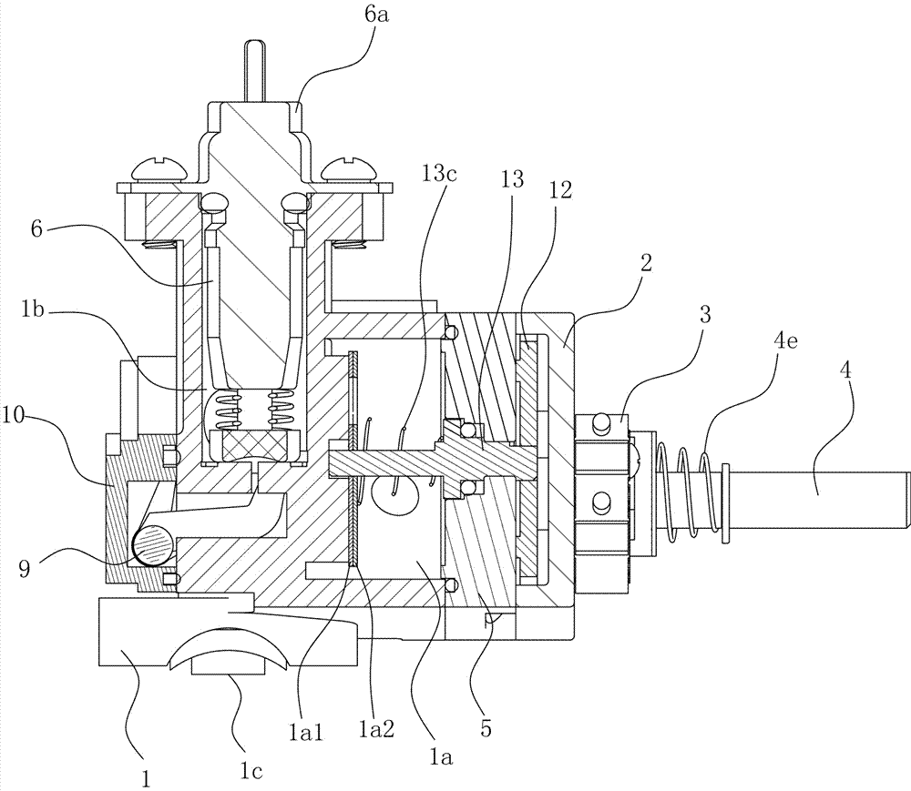
[0031] Figure 10 to Figure 13 It is the second embodiment of the present invention. The difference between embodiment 2 and embodiment 1 is that the valve body 1 of embodiment 2 is provided with two air outlets, and the valve core 7 is provided with two interconnected ventilation grooves. The air sheet 1a1 is provided with a through hole I, the through hole I is composed of a ventilation part and a gas distribution part, the ventilation part is a fan-shaped through hole 1a1a', and the gas distribution part includes a left gas distribution part and a right gas distribution part The left air distribution part is composed of interconnected fan-shaped through-holes A'B' and fan-shaped through-holes B'A', and the right air distribution part is composed of interconnected fan-shaped through-holes C'C' and Composed of fan-shaped through holes D'D', the width of each fan-shaped through hole in the gas distribution part along its radial direction is fan-shaped through-hole A'B'>fan-sha...

Embodiment 3

[0033] Embodiment 3 is basically the same as Embodiment 2, except that the width of the left air distribution part on the first air distribution plate 1a1 in embodiment 3 gradually increases along the direction of rotation of the air distribution plate, and the width of the right air distribution part along the direction of the air distribution plate The direction of rotation gradually narrows.

[0034] Compared with the prior art, the present invention has the following beneficial effects: the present invention adds an air distribution chamber to the valve body of the plunger valve; At least one side along the rotation direction of the gas distribution plate is provided with an air distribution groove connected with the air hole. The air distribution groove extends along the rotation direction of the gas distribution plate. The air distribution groove and the air hole can be partially or completely covered when the gas distribution plate rotates. In the air inlet in the air d...


PUM


Abstract

The invention discloses a plug valve. A gas distributing cavity is additionally arranged on a valve body of the plug valve; a gas distributing plate is arranged in the gas distributing cavity; a vent hole is formed in the gas distributing plate; a gas distributing slot which communicates with the vent hole is formed in at least one side, in the rotation direction of the gas distributing plate, of the vent hole; the gas distributing slot extends in the rotation direction of the gas distributing plate; when the gas distributing slot and the vent hole rotate along with the gas distributing plate, a gas inlet which is formed in the gas distributing cavity and communicates with a gas source can be partially or completely covered; and the gas distributing plate is connected with a valve element through a transmission device, and synchronously rotates with the valve element. The shape of the gas distributing slot can be set, so that gas outlet is kept consistent within certain rotation angle, and therefore, a user conveniently regulates fire power of a gas stove, and does not need to stare at fire all the time to slowly regulate like a mode of regulating firepower by a conventional fuel gas valve.

Description

technical field [0001] The invention relates to the field of gas valves, in particular to a plug valve. Background technique [0002] Chinese cuisine is famous all over the world because of its variety. Chinese people have various requirements for heat in cooking, and different firepowers are used at different times to cook a dish. However, traditional gas stoves mostly use traditional plunger valves to adjust the firepower. Often, the firepower does not change much after the knob is turned for a long time, and it will suddenly change a lot when it continues to turn. The required firepower can only be reached within a small angle range. Require. When adjusting firepower like this, will stare at all the time, use very inconvenient. Contents of the invention [0003] In order to overcome the above defects and deficiencies, the present invention provides the following technical solutions: a plug valve, including a valve body, the valve body is provided with a spool accommo...

Claims


Application Information

Patent Timeline
IPC IPC(8): F16K11/085F16K3/08F16K3/34F16K27/06F16K31/06F16K31/53F24C3/12
CPCF16K3/085F16K3/34F16K11/0856F16K27/065F16K31/0603F16K31/535F24C3/126
Inventor 张伟国梁圣佶章永钏梁垚垚潘赛斌
Owner ZHEJIANG XINTAO ELECTRONICS MACHINERY
Why Eureka
Try Eureka