Exhaust valve performance test system and test method

A test system and exhaust valve technology, which is used in the testing of mechanical parts, the testing of machine/structural parts, and measuring devices. Measure accuracy, avoid wasteful effects

Active Publication Date: 2017-06-20
HEFEI GENERAL MACHINERY RES INST
View PDF7 Cites 6 Cited by
  • Summary
  • Abstract
  • Description
  • Claims
  • Application Information

AI Technical Summary

Problems solved by technology

The flowmeter in the existing exhaust valve performance testing device has a single range and can only be tested for exhaust valves with specific caliber specifications

Method used


Image

  • Exhaust valve performance test system and test method

Examples


Embodiment 1

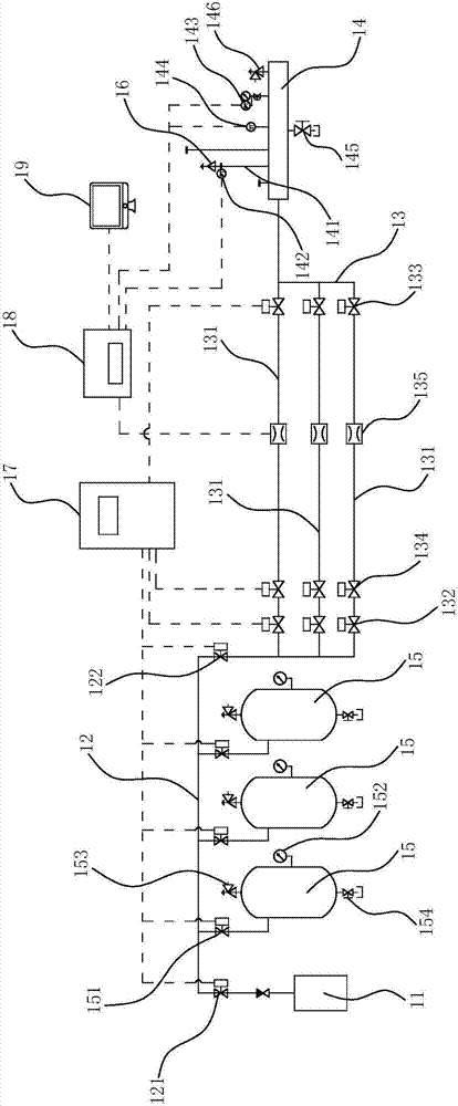
[0031] Such as figure 1 As shown, the exhaust valve performance test system in the present invention includes a compressor 11, a gas storage section pipeline 12, a flow measurement section pipeline 13 and a test container 14 connected in sequence along the gas flow direction, and the compressor 11 is connected to the gas storage section. A main valve 121 is arranged between the section pipelines 12; the gas storage section pipeline 12 is connected with a plurality of gas storage tanks 15 arranged side by side; There is a switch valve 1 151; the flow measurement section pipeline 13 includes a plurality of branch pipelines 131 with different calibers and arranged side by side, each branch pipeline 131 inlet is provided with a switch valve 2 132, and each branch pipeline 131 outlet is provided with On-off valve three 133, the branch pipeline 131 is also provided with a pressure regulating valve 134 and a flow meter 135; the test container 14 is connected with an installation pipe...

Embodiment 2

[0041] The test method of the above-mentioned exhaust valve performance test system comprises the following steps:

[0042] S1, close the main valve two 122, open the main valve one 121 and the switch valve one 151, start the compressor 11, inflate each air storage tank 15 through the compressor 11, after each air storage tank 15 is full, Close the on-off valve one 151 and the main valve one 121;

[0043] S2. According to the caliber parameters of the tested valve 16, determine the number of gas storage tanks 15 required for the test, the number and the caliber of the branch pipelines 131;

[0044] S3, open the main valve two 122 and the on-off valve one 151 of each gas storage tank 15 required for the test, open the required branch pipeline 131 inlet end on-off valve two 132, pressure regulating valve 134 and outlet end on-off valve three 133, After the medium flows out from the gas storage tank 15, it first enters the branch pipeline 131 and then flows into the test contain...


PUM


Abstract

The invention relates to an exhaust valve performance test system and a test method. The test system comprises a compressor, a gas storage section pipeline, a flow measurement section pipeline and a test container, wherein the compressor, the gas storage section pipeline, the flow measurement section pipeline and the test container are successively connected in the gas flow direction. A first total valve is arranged between the compressor and the gas storage section pipeline. A number of parallel gas storage tanks are connected with the gas storage section pipeline. A first switching valve is arranged between the gas storage tanks and the gas storage section pipeline. The flow measurement section pipeline comprises a number of branch pipelines with different calibers, wherein the branch pipelines are arranged in parallel. A second switching valve is arranged in the inlet of each branch pipeline. A third switching valve is arranged in the outlet of each branch pipeline. Each branch pipeline is provided with a pressure regulating valve and a flowmeter. The test container is connected with a mounting pipe used for mounting a tested valve. A first pressure sensor is arranged in the inlet of the tested valve. The exhaust valve performance test system provided by the invention is extensible, and can support subsequent tests of larger exhaust valves by increasing the number of gas storage tanks or the number of branch pipelines.

Description

technical field [0001] The invention belongs to the field of exhaust valves, and in particular relates to an exhaust valve performance testing system and a testing method. Background technique [0002] The exhaust valve is usually installed at the highest point of the water supply pipeline to discharge the gas precipitated in the water in the pipeline to avoid head loss caused by gas accumulation in the pipeline. The exhaust valve is a key component to ensure smooth exhaust and safe operation of the water supply pipeline. The flowmeter in the existing exhaust valve performance testing device has a single measuring range, and can only be tested for exhaust valves with specific caliber specifications. Therefore, those skilled in the art urgently need to provide a system that is scalable and capable of performing performance tests on exhaust valves of various calibers. Contents of the invention [0003] In order to solve the above technical problems, the present invention pr...

Claims


Application Information

Patent Timeline
Patent Type & Authority Applications(China)
IPC IPC(8): G01M13/00
CPCG01M13/00
Inventor 张继伟黄健王剑彭林范宜霖雷艳张绍华
Owner HEFEI GENERAL MACHINERY RES INST
Why Eureka
Try Eureka