A Phase Shift Compensation Method for Single Resistor Current Sampling

A technology of current sampling and compensation method, applied in the direction of measuring current/voltage, measuring electrical variables, instruments, etc., can solve the problems of inaccurate current sampling, change of duty cycle, inaccurate control, etc., to achieve flexible sampling, simple algorithm, Wide range of effects

Active Publication Date: 2019-04-02
苏州半唐电子有限公司
View PDF8 Cites 0 Cited by
  • Summary
  • Abstract
  • Description
  • Claims
  • Application Information

AI Technical Summary

Problems solved by technology

This overcomes the problem of inaccurate control due to duty cycle changes when the sampling time of the traditional scheme is short
However, under the extreme working condition of the motor running at high speed, the existing technology has a sampling blind zone that cannot meet the condition of being greater than the minimum current sampling time Tmin no matter how the phase is shifted, resulting in inaccurate current sampling
[0004] Another example is the Chinese invention patent with the publication number CN105450094A disclosing a current sampling method and air-conditioning equipment. By judging whether the sampling current is an effective current, if it is determined that the sampling current corresponding to the nth sampling is invalid, the n-1th sampling The current estimated value of the sampling current is used as the sampling current of the nth sampling; for another example, the Chinese invention patent whose publication number is CN106208826A also discloses an overmodulation control method for a permanent magnet synchronous motor without a three-phase current sensor. When sampling with a single resistor, the reference voltage is modified, and all three phases are moved; the algorithm is not only complicated, but also under the extreme working condition of the motor running at high speed, there is a sampling blind zone that cannot meet the condition of being greater than the minimum current sampling time Tmin no matter how the phase is shifted. lead to inaccurate current sampling

Method used


Image

  • A Phase Shift Compensation Method for Single Resistor Current Sampling
  • A Phase Shift Compensation Method for Single Resistor Current Sampling
  • A Phase Shift Compensation Method for Single Resistor Current Sampling

Examples


Embodiment Construction

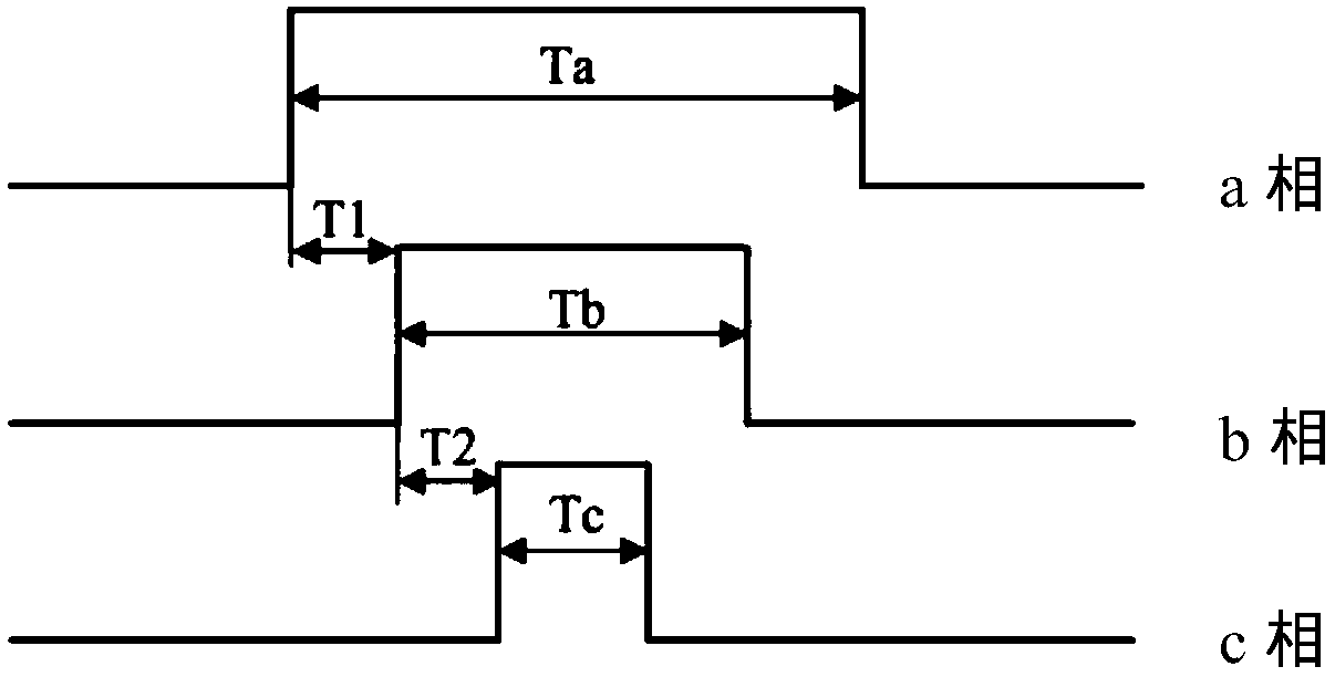
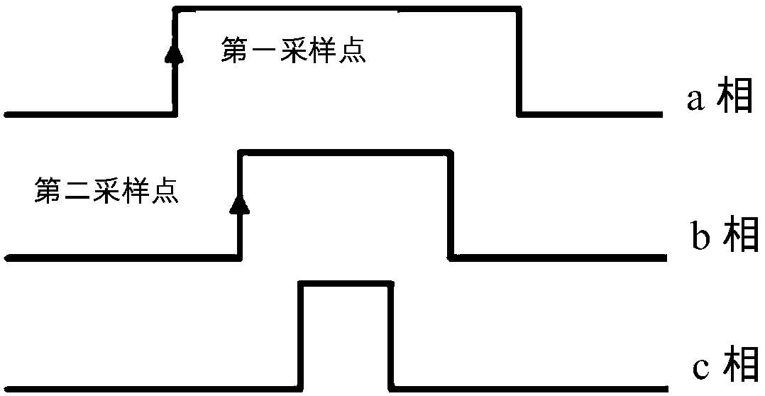
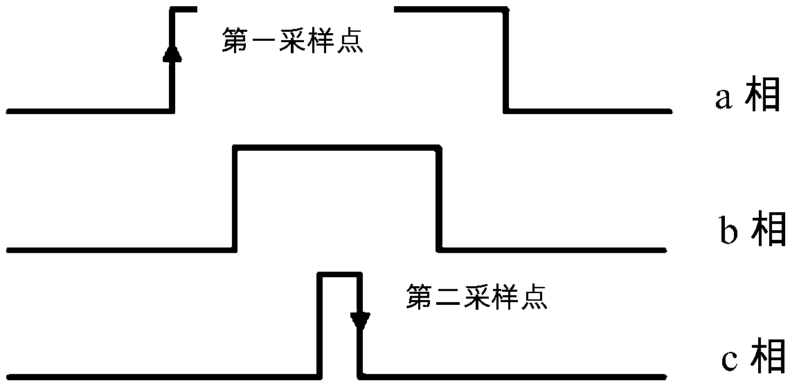
[0032] The embodiment of the present invention discloses a phase-shift compensation method for single-resistance current sampling. The method includes the following steps: S10), determining T1 and T2 according to Ta, Tb, and Tc, wherein T1 is the matching time of the first sampling point, and T2 is The second sampling point matches the time. Ta is the duty cycle time corresponding to the maximum duty cycle in the a, b, and c three-phase PWM signals, and Tb is the corresponding time in the middle of the duty cycle in the a, b, and c three-phase PWM signals. Duty ratio time, Tc is the duty ratio time corresponding to the minimum duty ratio in the a, b, c three-phase PWM signals; S20), judge whether T1+T2 is greater than 2*Tmin, if yes, execute step S31), If not, execute step S32), wherein, Tmin is the minimum current sampling time; S31), judge whether T1 is greater than or equal to Tmin, if yes, execute step S41), if not, shift the intermediate phase of the duty ratio Execute st...


PUM


Abstract

The invention discloses a phase shift compensation method for single resistance current sampling. The method comprises the steps of (S20) judging whether T1+T2 is larger than 2*Tmin or not, executing a step S(31) if so, and executing a step (S32) if not; (S31) judging whether T1 is larger than or equal to Tmin, executing a step (S41) if so, and carrying out phase shift compensation on a middle phase and then executing a step (S41) if not, (S32) judging whether T1 is larger than or equal to Tmin, and executing a step (S42) if so, and carrying out phase shift compensation on a maximum phase and then executing a step (S42) if not; (S41) judging whether T2 is larger than or equal to Tmin, executing a step (S51) if so, and carrying out phase shift compensation on a middle phase and then executing a step (S51) if not; (S42) judging whether T2 is larger than or equal to Tmin, executing a step (S52) if so, and carrying out phase shift compensation on a minimum phase and then executing a step (S52) if not, (S51) sampling at two sides of the maximum phase and the minimum phase, and (S52) sampling at the same sides of the maximum phase and the middle phase. According to the phase shift compensation method, T1 or T2 is always larger than the minimum current sampling time Tmin, and thus a sampling blind area is completely eliminated.

Description

technical field [0001] The invention relates to the field of single-resistance current sampling, in particular to a phase-shift compensation method for single-resistance current sampling. Background technique [0002] The working principle of the single-resistor current sampling technology is to use the sampling resistor installed on the DC bus to realize the three-phase current sampling of the motor through an appropriate algorithm. Compared with the traditional two-resistor sampling technology, this technology saves one sampling channel, which can further reduce the cost and size of the motor controller. However, the single-resistor current sampling technology has a situation where the controller MCU is less than the minimum current sampling time Tmin, so it is necessary to perform phase shift compensation on the duty cycle. [0003] In order to ensure that the controller MCU satisfies the condition of being greater than the minimum sampling time Tmin, there have been man...

Claims


Application Information

Patent Timeline
Patent Type & Authority Patents(China)
IPC IPC(8): G01R19/25
CPCG01R19/2506
Inventor 何志明贺增向大为
Owner 苏州半唐电子有限公司
Why Eureka
Try Eureka