Pyrotechnic circuit breaker

A circuit breaker and pyrotechnic technology, applied in the field of pyrotechnic starters, can solve the problems of large volume and inconvenience, and achieve the effect of enhancing efficiency, speed and compactness

Active Publication Date: 2017-06-20
AUTOLIV DEV AB
View PDF6 Cites 4 Cited by
  • Summary
  • Abstract
  • Description
  • Claims
  • Application Information

AI Technical Summary

Problems solved by technology

But the disadvantage of this is that if the system uses high voltage / strong current to cut off the circuit, it will cause inconvenience due to its large size

Method used


Image

  • Pyrotechnic circuit breaker
  • Pyrotechnic circuit breaker
  • Pyrotechnic circuit breaker

Examples


Embodiment Construction

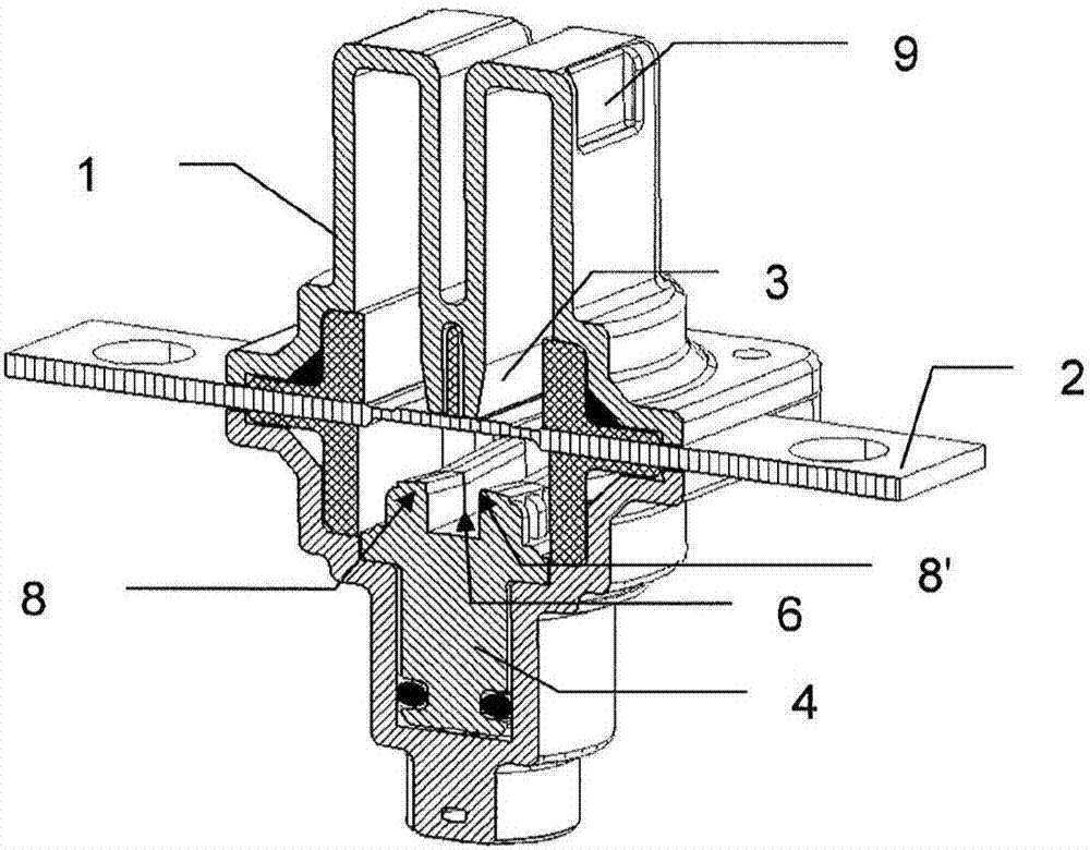
[0072] figure 1 A perspective view of a circuit breaker according to the invention is shown in section. A conductor 2 traverses a part of the housing 1, the ends of which form the two connection terminals of the circuit breaker. The circuit breaker includes a punch 4 and an impact die 3. Before the circuit breaker works, the above two parts are placed on both sides of the conductor 2, such as figure 1 shown.

[0073] Punch 4 has in its upper part facing impact die 3 a groove delimited by two cutting edges 8 and 8 ′, and a channel 6 which is a vertical groove connecting cutting edge 8 and the bottom of the groove of punch 4 . In addition there is another channel (not visible) connecting the cutting edge 8' with the bottom of the groove of the punch 4. Channel 6 will function in conjunction with image 3 Details are given in the relevant paragraphs.

[0074] In the figure, the punch 4 is in a first position, wherein the electrical conductor 2 is intact and not severed. In...


PUM


Abstract

A pyrotechnic circuit breaker comprising: a casing (1) with at least one cutoff chamber (7, 7'), at least one electric conductor (2), at least one punch (4) arranged to cut said at least one electric conductor (2), at least one pyrotechnic actuator, an insert (31) overmoulded over said at least one electric conductor (2), characterized in that the casing (1) comprises a first casing portion and a second casing portion, with at least one sealing means between the insert (31) and one of the first casing portion and / or second casing portion in order to seal said at least one cutoff chamber (7, 7').

Description

[0001] This application is an application for an invention patent with the Chinese application number "201580007126.4", the PCT international application number "PCT / EP2015 / 052277", the international application date is February 4, 2015, and the invention name is "pyrotechnic circuit breaker". Divisional application. technical field [0002] The present invention generally relates to a circuit breaker comprising a pyrotechnic starter adapted to be mounted on a motor vehicle, especially an electric motor vehicle. Background technique [0003] For such EVs, ways to cut the wires connecting the energy storage device (battery, supercapacitor, etc.) to the rest of the car must be considered in advance, for example in the event of an accident to keep other devices safe. Due to the characteristics of the relevant power and energized lines, an arc will be generated when the power is cut off. If it is not controlled, it will cause partial or even overall power failure of the line. J...

Claims


Application Information

Patent Timeline
Patent Type & Authority Applications(China)
IPC IPC(8): H01H39/00
Inventor F·戈迪纳塔阿兰·马涅P·雅科
Owner AUTOLIV DEV AB
Why Eureka
Try Eureka