Cell winding needle mechanism and cell winding method

A technology of rolling needles and cells, applied in circuits, electrical components, secondary batteries, etc., can solve the problems of wrinkling and deformation of cells, large difference between the short axis and long axis, and bending damage of the tabs of the cell, etc. To solve the problem of speed increase, reduce the fluctuation of tension and improve production efficiency

Pending Publication Date: 2017-06-20
GEESUN AUTOMATION TECH
View PDF5 Cites 14 Cited by
  • Summary
  • Abstract
  • Description
  • Claims
  • Application Information

AI Technical Summary

Problems solved by technology

During production, due to the radian of the shape of the elliptical winding needle, the tabs of the battery core will be bent and damaged. After the battery core is wound, it will be flattened and blanked, which will easily cause wrinkling and deformation inside the battery core.
Another kind of flat diamond-shaped needle winding mechanism, due to the large difference between the short axis and the long axis, the winding pro

Method used


Image

  • Cell winding needle mechanism and cell winding method
  • Cell winding needle mechanism and cell winding method
  • Cell winding needle mechanism and cell winding method

Examples


Embodiment Construction

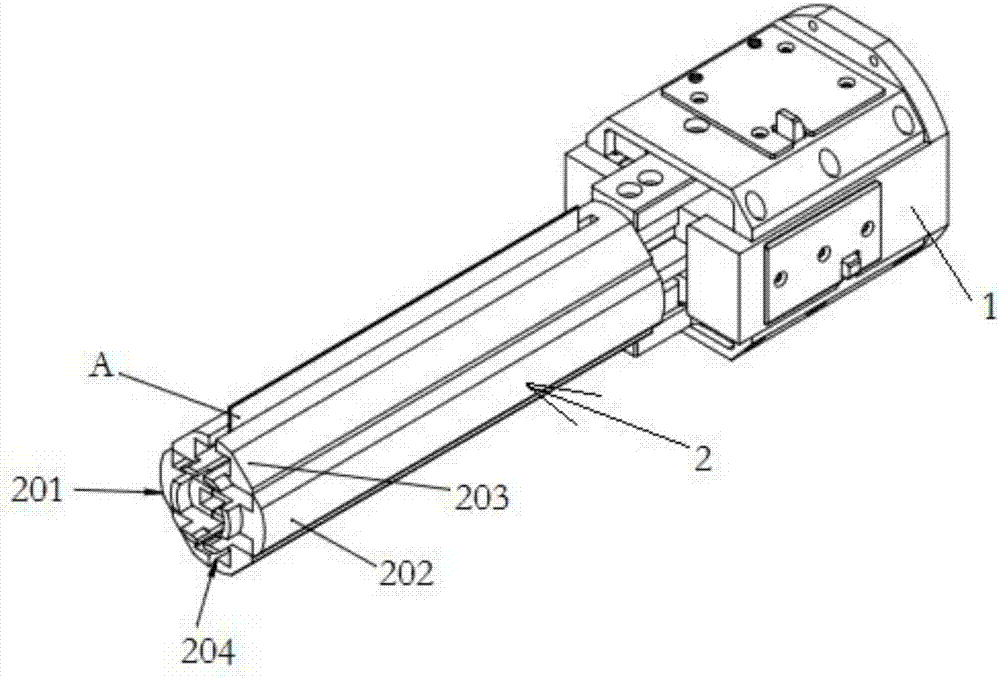
[0036] The present application will be described in further detail below through specific embodiments in conjunction with the accompanying drawings. The present application can be implemented in many different forms, and is not limited to the implementation manner described in this embodiment. The purpose of providing the following specific embodiments is to facilitate a clearer and more thorough understanding of the disclosure of the present application, wherein the words indicating orientation such as up, down, left, and right are only for the positions of the structures shown in the corresponding drawings.

[0037] However, those skilled in the art may recognize that description of one or more of the specific details may be omitted, or other methods, components or materials may also be used. In some instances, some implementations were not described or described in detail.

[0038] In addition, the technical features and technical solutions described herein can also be com...


PUM


Abstract

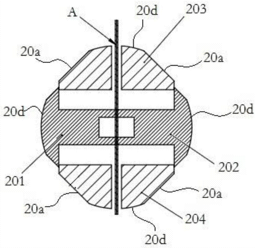
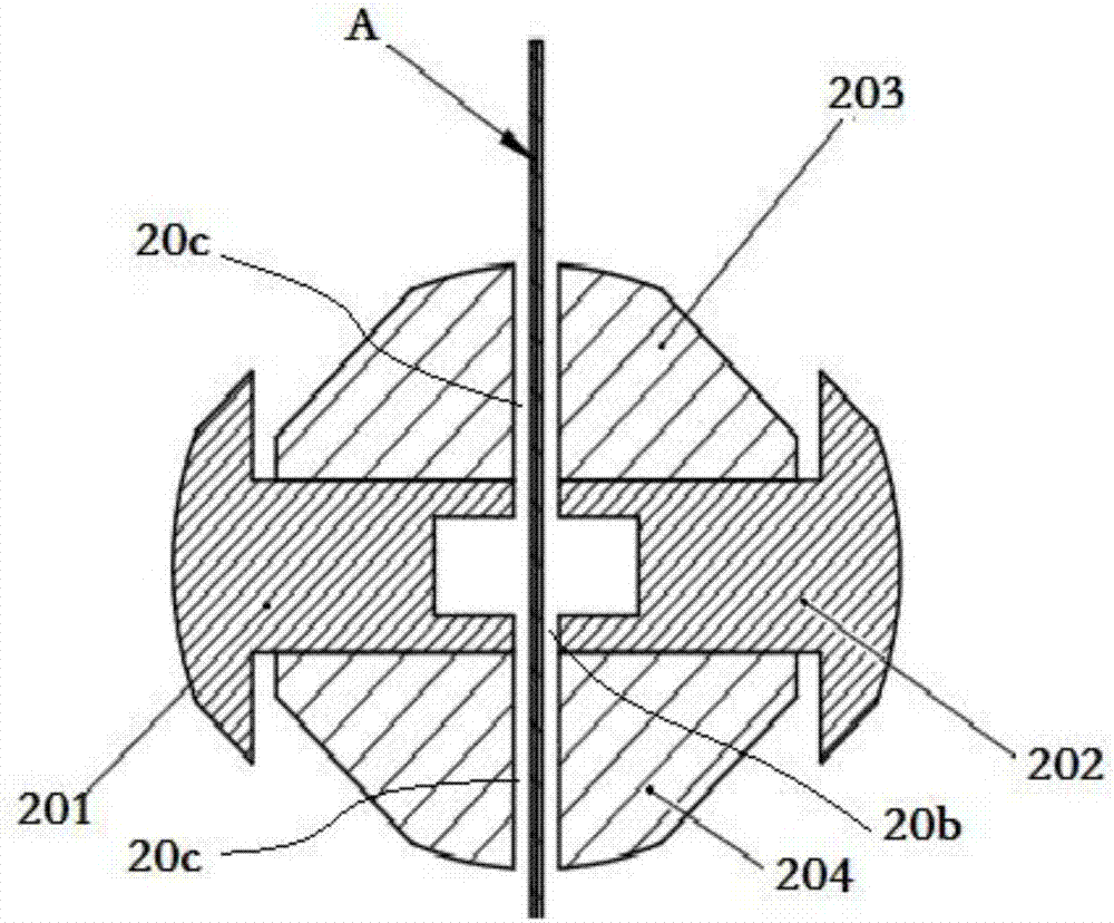
The invention discloses a cell winding needle mechanism and a cell winding method. The cell winding needle mechanism comprises a winding needling base and a winding needle connected with the winding needling base; a tab positioning plane is arranged on the winding surface of the winding needling; the winding needling comprises a left needle body and a right needle body which are symmetrically arranged left and right, and an upper needle body and a lower needle body which are symmetrically arranged up and down; a clamping slit which can be used for tightly clamping/loosening a diaphragm is formed between the left needle body and the right needle body; an avoidance slit which is connected with the clamping slit is formed in each of the upper needle body and the lower needle body in a run-through manner separately; and the winding needle base is provided with a left and right needle body displacement driving apparatus which drives the left needle body and the right needle body to move in left and right directions to be far from each other/close to each other, and an upper and lower needle body displacement driving apparatus which drives the upper needle body and the low needle body to move in up and down directions to be far from each other/close to each other. When the cell winding needle mechanism is adopted for winding, the tab is tightly attached to the plane of the winding needle, so that the tab is not bent and damaged easily; the long axis and the short axis of the winding needle are low in difference, so that tension fluctuation is relatively low; and therefore, over high shaking on a pole piece can be avoided, and production efficiency is improved.

Description

technical field [0001] The present application relates to the field of lithium battery production equipment, in particular to a battery core winding mechanism and a battery winding method. Background technique [0002] In the existing lithium battery equipment, the winding needle of the winding machine is an important part of the winding of the battery core, and the shape of the winding needle affects the winding speed of the battery core and the quality of the battery core. Most of the current winding machines adopt elliptical and flat rhombic needle rolling mechanisms. During production, the radian of the shape of the elliptical winding needle will cause bending damage to the tabs of the battery core. After the battery core is wound, it will be flattened and blanked, which will easily cause wrinkling and deformation inside the battery core. Another type of flat diamond-shaped needle winding mechanism, due to the large difference between the short axis and the long axis, t...

Claims


Application Information

Patent Timeline
IPC IPC(8): H01M10/0587H01M6/14
CPCH01M6/14H01M10/0587Y02E60/10Y02P70/50
Inventor 黄梅宝阳如坤魏宏生
Owner GEESUN AUTOMATION TECH
Why Eureka
Try Eureka