
Silicon wafer wire cutting machine

A technology of wire cutting machine and silicon wafer, which is applied to fine working devices, stone processing equipment, manufacturing tools, etc. It can solve the problems of heavy wire wheel weight, low cutting efficiency, and large wire bobbin jump, so as to reduce wire mesh pull Empty, improve cutting efficiency, and increase cutting efficiency

Pending Publication Date: 2017-11-24
江阴市展照科技有限公司
View PDF10 Cites 4 Cited by
  • Summary
  • Abstract
  • Description
  • Claims
  • Application Information

AI Technical Summary

Problems solved by technology

[0002] For traditional wire cutting equipment for silicon wafers, the installation method of the wire drum is vertical installation, the weight of the wire wheel is large, the stroke of the wire is large, and the jump of the wire drum is large; The larger the number of guide wheels; the cutting head of the silicon wafer wire cutting equipment, the distance between the two main rollers is relatively wide, and the relatively wide center distance is wide, unstable, easy to break, and low cutting efficiency

Method used


Image

  • Silicon wafer wire cutting machine
  • Silicon wafer wire cutting machine
  • Silicon wafer wire cutting machine

Examples


Embodiment Construction

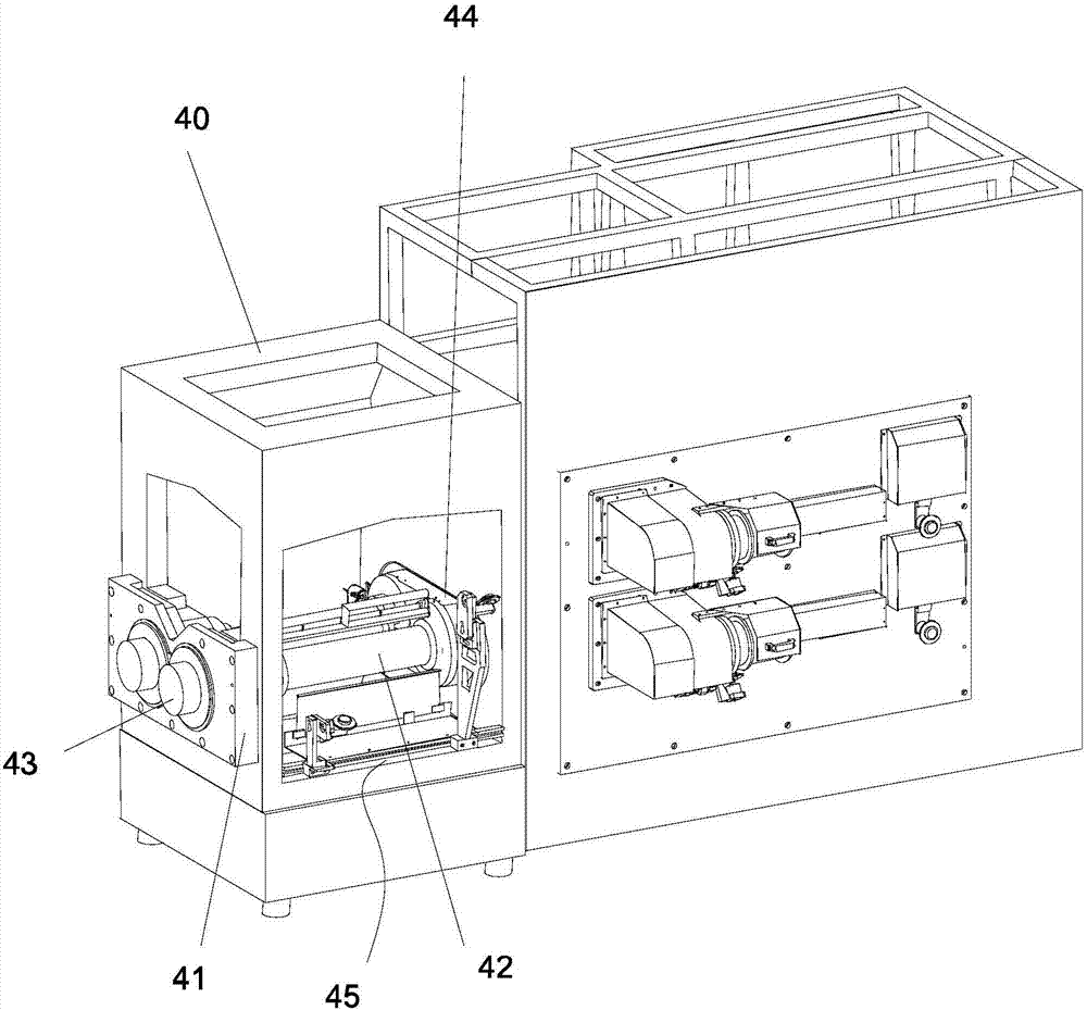
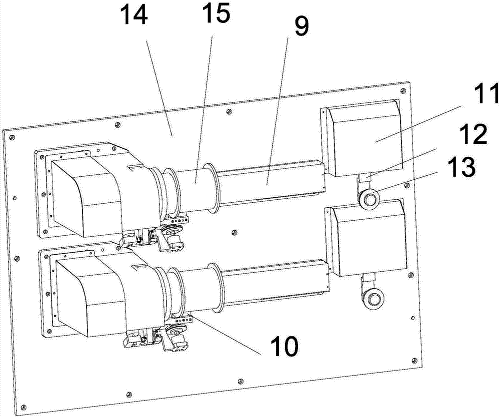
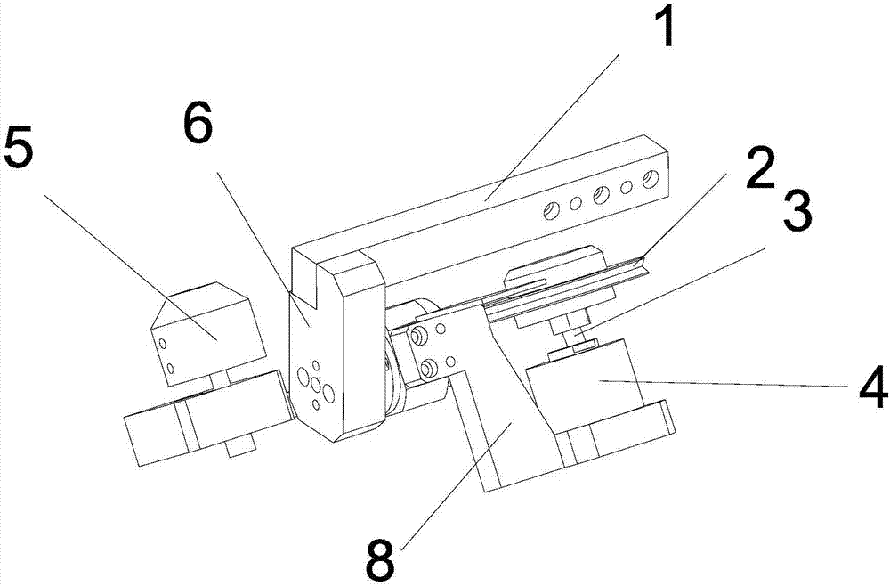
[0016] Such as Figure 1-4 As shown, a wire cutting machine for silicon wafers includes a frame 40, a cutting chamber located at the front of the frame, and a wire barrel chamber positioned behind the cutting chamber. The cutting chamber is provided with a cutting head and a wire reel tooling 45. The wire spool room includes a main board 14, a take-up and pay-off reel unit, two guide wheel frocks respectively located under the take-up and pay-off reels 15, a guide reel frock moving seat 10 connected to the guide pulley frock, and two traversing frames 9 , two tension arm motors, the tension arm 12 that links to each other with the tension arm motor, the tension arm guide wheel 13 that is located at the lower end of the tension arm, the horizontal movement frame 9 is set horizontally, and the horizontal movement frame 9 bottom is provided with a horizontal The guide wheel frock moving seat slide rail, the guide wheel frock moving seat 10 can move laterally along the slide rail;...


PUM


Abstract

The invention discloses a silicon wafer wire cutting machine. The silicon wafer wire cutting machine comprises a frame, a cutting chamber and a wire barrel chamber. The cutting chamber is internally provided with a cutting head and a winding and unwinding wheel tool. The wire barrel chamber comprises a main plate, a winding and unwinding wheel unit, two wire guiding wheel tools arranged below winding and unwinding wheels, wire guiding wheel tool movable bases connected with the wire guiding wheel tools, two transverse movement frames, two tension arm motors, tension arms connected with the tension arm motors, and tension arm guiding wheels arranged at the lower ends of the tension arms, and the transverse movement frames are horizontally arranged. The silicon wafer wire cutting machine has the beneficial effects that the guiding wheel arrangement structure is optimized, the wire barrel installing manner is horizontal installation, the winding displacement load of horizontal installation is uniform, and the number of guiding wheels is reduced; and due to reduction of the number of the wire guiding wheels, the breaking tension of a steel wire is increased firstly, and then fluctuation of tension entering a wire net becomes small; and jumping of the wire barrel is weak, winding displacement is more stable, and arm swinging is stable when the tension arms run. By means of the silicon wafer wire cutting machine, broken wires are effectively monitored, and wire net empty pulling and other losses caused by wire breaking are reduced.

Description

technical field [0001] The invention belongs to the technical field of silicon wafer wire cutting, in particular to a silicon wafer wire cutting machine. Background technique [0002] For traditional wire cutting equipment for silicon wafers, the installation method of the wire drum is vertical installation, the weight of the wire wheel is large, the stroke of the wire is large, and the jump of the wire drum is large; The larger the number of guide wheels; the cutting head of the silicon wafer wire cutting equipment, the distance between the two main rollers is relatively wide, and the relatively wide center distance is wide, unstable, easy to break, and low cutting efficiency. Contents of the invention [0003] In order to solve the above-mentioned problems existing in the prior art and actual conditions, the present invention provides a silicon wafer wire cutting machine, comprising a frame, a cutting chamber located at the front of the frame, and a wire barrel chamber p...

Claims


Application Information

Patent Timeline
Patent Type & Authority Applications(China)
IPC IPC(8): B28D5/04B28D5/00
CPCB28D5/0058B28D5/045
Inventor 李磊
Owner 江阴市展照科技有限公司
Learn More