Filter

A filter and coupling window technology, applied in the filter field, can solve problems such as complex filter structure, and achieve the effect of simple structure and constant bandwidth

Active Publication Date: 2017-06-20
成都德是和通信科技有限公司
View PDF3 Cites 1 Cited by
  • Summary
  • Abstract
  • Description
  • Claims
  • Application Information

AI Technical Summary

Problems solved by technology

[0005] In view of this, the purpose of the embodiments of the present invention is to provide a filter to solve the problem in the prior art that th

Method used


Image

  • Filter
  • Filter
  • Filter

Examples


Embodiment Construction

[0038] In order to make the purpose, technical solutions and advantages of the embodiments of the present invention clearer, the technical solutions in the embodiments of the present invention will be clearly and completely described below in conjunction with the drawings in the embodiments of the present invention. Obviously, the described embodiments are only It is a part of embodiments of the present invention, but not all embodiments. The components of the embodiments of the invention generally described and illustrated in the figures herein may be arranged and designed in a variety of different configurations. Accordingly, the following detailed description of the embodiments of the invention provided in the accompanying drawings is not intended to limit the scope of the claimed invention, but merely represents selected embodiments of the invention. Based on the embodiments of the present invention, all other embodiments obtained by those skilled in the art without making...


PUM


Abstract

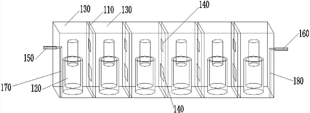
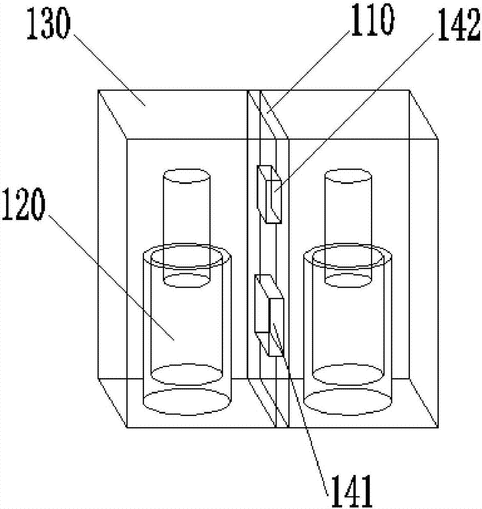
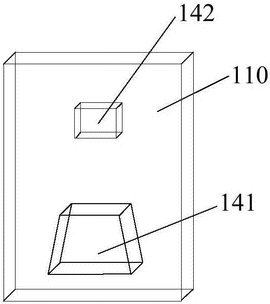
The invention provides a filter. The filter comprises a filter cavity, at least one partition plate and resonant rods, wherein the partition plate is arranged in the filter cavity and is parallel to a side wall of the filter cavity, the filter cavity is partitioned to a plurality of resonant cavities, the resonant rod is arranged in each resonant cavity, the resonant rods are parallel to the partition plate, and coupling windows are formed in two ends of the partition plate and are used for achieving cavity coupling of the filter. In the filter, a coupling adjustment device is not needed to be additionally arranged, and the filter is simple in structure.

Description

technical field [0001] The present invention relates to the technical field of communications, and in particular, to a filter. Background technique [0002] A TV channel synthesizer is a device that allows multiple transmitters of different channels to share the same broadband antenna and transmit their programs without interfering with each other. The band-pass filter is a key component of the TV channel synthesizer. The filter frequency range in the field of radio and television includes FM broadcasting (Frequency Modulation, FM), the frequency range is 87 ~ 108MHz, very high frequency (Very High Frequency, VHF), the frequency range is 179 ~ 219MHz, ultra high frequency (Ultra High Frequency) , UHF), the frequency range is 470 ~ 806MHz, among them, the signal bandwidth of FM is very narrow, the filter bandwidth used is about 300 ~ 600K, VHF and UHF are both TV bands, and the filter bandwidth is 8MHz. [0003] The frequency division is different in different places, and th...

Claims


Application Information

Patent Timeline
IPC IPC(8): H01P1/207
CPCH01P1/207
Inventor 隋强王轶冬王典进杨刚马骏刘学礼
Owner 成都德是和通信科技有限公司
Why Eureka
Try Eureka