
A Voltage Source Transconductance Mode Control Circuit

A mode control and control circuit technology, applied in control/regulating systems, electrical components, regulating electrical variables, etc., can solve problems such as increasing output impedance, reducing voltage source bandwidth, and voltage source not adapting to the electrical performance requirements of loads, etc. The effect of constant loop bandwidth and constant output impedance

Active Publication Date: 2017-07-18
SHENZHEN AEROSPACE NEW POWER TECH
View PDF6 Cites 0 Cited by
  • Summary
  • Abstract
  • Description
  • Claims
  • Application Information

AI Technical Summary

Problems solved by technology

[0007] The reduction of the number of parallel power supply sub-modules will cause the bandwidth of the voltage source to decrease and the output impedance to increase, which is not suitable for some applications with high-bandwidth load characteristics. There are no measures to deal with the decrease of bandwidth and output impedance, and there will be situations where the voltage source can output power but cannot meet the electrical performance requirements of some loads;

Method used


Image

  • A Voltage Source Transconductance Mode Control Circuit
  • A Voltage Source Transconductance Mode Control Circuit
  • A Voltage Source Transconductance Mode Control Circuit

Examples


Embodiment Construction

[0018] The present invention will be further described below in conjunction with the accompanying drawings and specific embodiments.

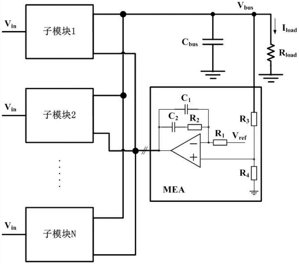
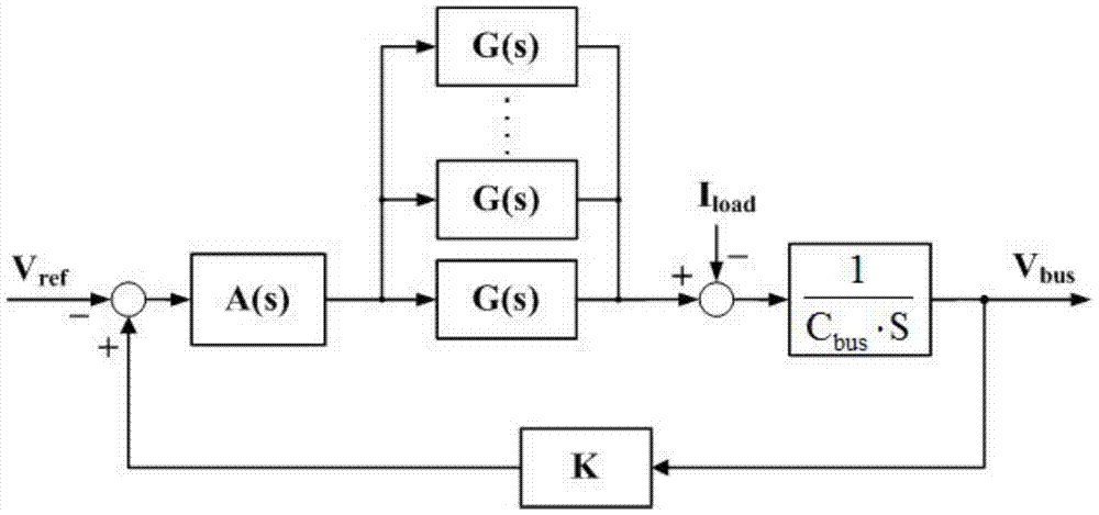
[0019] as follows figure 2 As shown, it is a closed-loop control block diagram of an existing transconductance mode-controlled voltage source, which includes: N voltage-controlled current source sub-modules connected in parallel, whose outputs are connected to the output end of the bus bar; the voltage sampling circuit is connected to the output end of the bus bar To sample the bus output voltage, the external error calculation and transmission circuit receives the voltage sampling signal and compares it with the reference voltage value to calculate the error voltage signal, and converts the error voltage signal with the voltage transfer function A(s) and divides it into the same N circuits, respectively It is connected with the respective voltage control signal terminals of the N sub-modules in a one-to-one correspondence. Among them, the vo...


PUM


Abstract

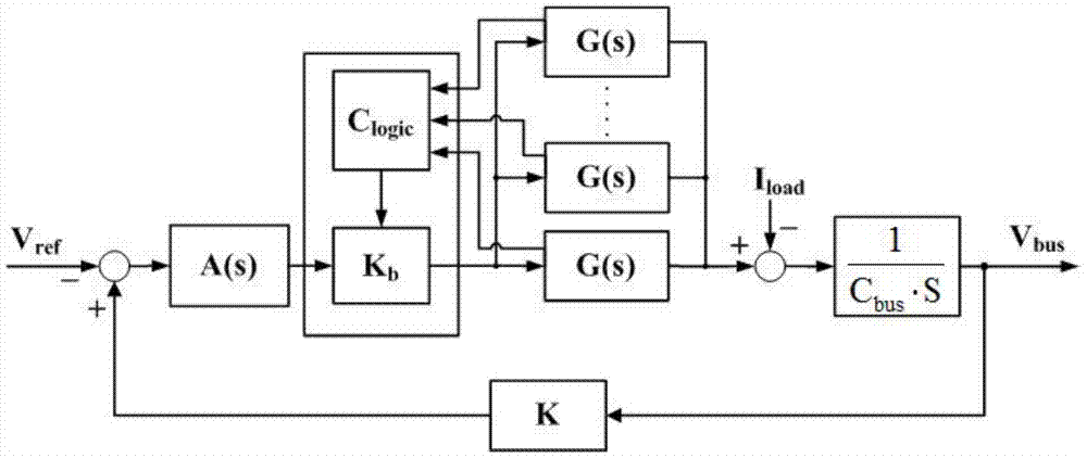
The invention provides a transconductance mode control circuit of a voltage source, comprising: N voltage-controlled current source sub-modules connected in parallel, the respective output ends of the N sub-modules are connected to the output end of the bus bar, and the voltage sampling circuit samples the output voltage of the bus bar , the external error calculation and transmission circuit receives the voltage sampling signal and compares it with the reference voltage signal to generate an error voltage signal and then outputs it to the transconductance compensator; the output of the transconductance compensator corresponds to the respective voltage control signal terminals of the N sub-modules ground connection; the controlled end of the transconductance compensator receives the on / off state signal of each sub-module; the transconductance compensator judges the number of sub-modules in the working state according to the on-off state signal of each sub-module and adjusts it proportionally according to the number The transconductance gain of the transconductance compensator. The invention enables the output bus voltage of the power supply to maintain constant bandwidth and output impedance even when the number of power supply sub-modules participating in parallel connection changes.

Description

technical field [0001] The circuit of the invention relates to a voltage source transconductance mode control circuit, and is mainly used in switching power supplies, linear power supplies and other fields using average current mode control. Background technique [0002] Transconductance mode (that is, average current mode) control, because it is easy to parallel redundant backup, strong anti-interference, single device, automatic current sharing, current limiting and other functions, is widely used in various voltage source transformations that use power sub-modules in parallel device. The bandwidth and output impedance of the voltage source are its key indicators. Due to the various requirements of the load characteristics connected to the voltage source, in order to ensure the application range of the voltage source, it is necessary to carry out the maximum envelope of the electrical performance index of the load under various working conditions. Design, focusing on the ...

Claims


Application Information

Patent Timeline
Patent Type & Authority Patents(China)
IPC IPC(8): H02M3/00H02M3/335
Inventor 付明刘锡洋
Owner SHENZHEN AEROSPACE NEW POWER TECH
Learn More