Multi-transimpedance constant-bandwidth ultralow-noise TIA

A constant bandwidth, ultra-low noise technology, applied in the direction of improving amplifiers to reduce noise effects, etc., can solve problems such as the inability to guarantee the overall performance of TIA, the large variation of optional transimpedance TIA bandwidth and noise, affecting the linearity of the sensitivity output signal, etc. Achieve the effect of ensuring sensitivity and linearity, increasing dynamic range, and meeting performance requirements

Active Publication Date: 2020-10-27
QIANDU TONGCHIP XIAMEN MICROELECTRONICS TECH CO LTD
View PDF7 Cites 1 Cited by
  • Summary
  • Abstract
  • Description
  • Claims
  • Application Information

AI Technical Summary

Problems solved by technology

[0017] The purpose of the present invention is to solve the problem that the commonly used optional transimpedance TIA has large bandwidth and noise changes, thereby affecting the sensitivity and the linearity of the output signal, and finally cannot guarantee the overall performance of the TIA, and provides a multi-transimpedance constant bandwidth ultra-low noise TIA

Method used


Image

  • Multi-transimpedance constant-bandwidth ultralow-noise TIA
  • Multi-transimpedance constant-bandwidth ultralow-noise TIA
  • Multi-transimpedance constant-bandwidth ultralow-noise TIA

Examples


specific Embodiment approach 1

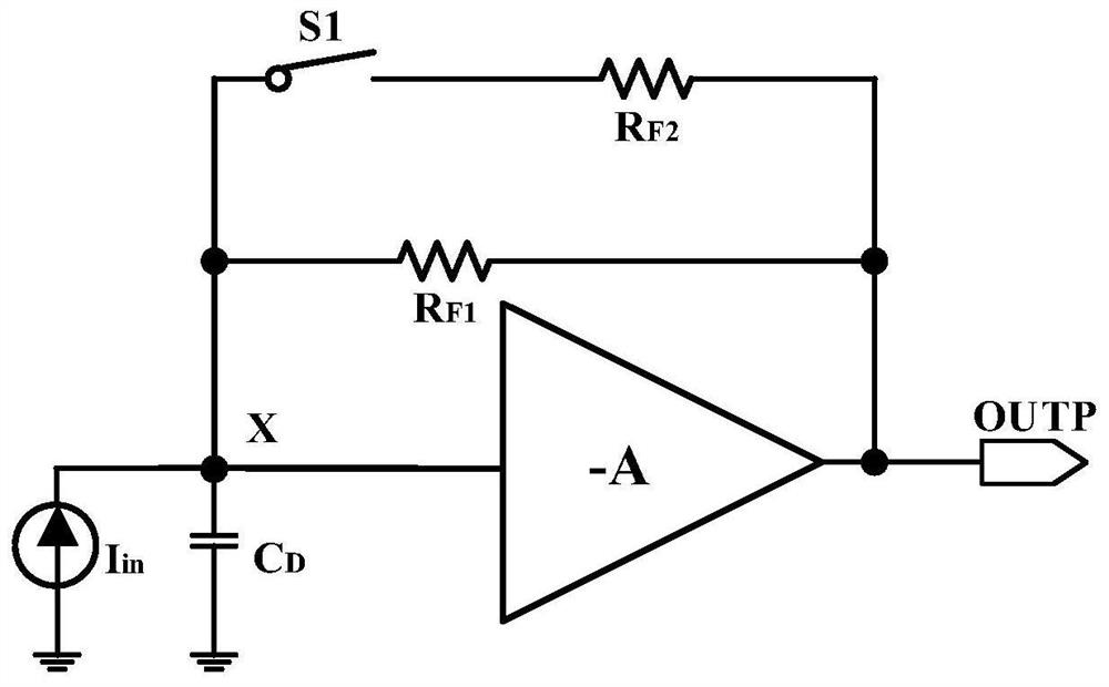
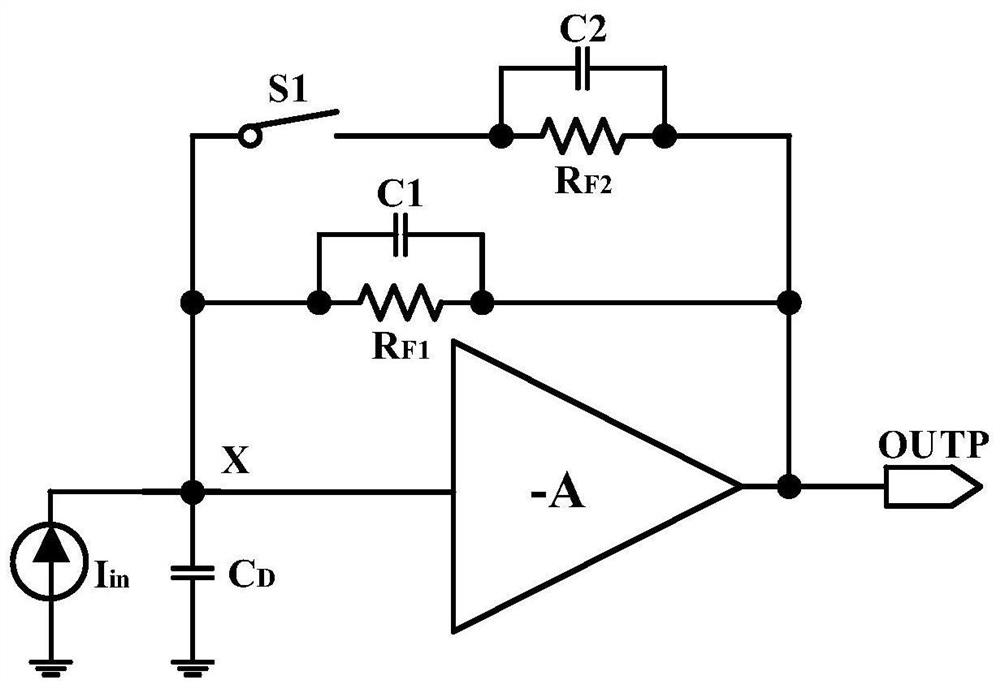
[0036] Specific implementation mode one: the following combination figure 2 Describe this embodiment, the multi-transimpedance constant bandwidth ultra-low noise TIA described in this embodiment, in figure 1 The conventional multi-transimpedance TIA shown is improved on the basis of the transimpedance R F1 Capacitor C1 is connected in parallel at both ends, and the transimpedance R F2 Capacitor C2 is connected in parallel at both ends, and the sizes of capacitors C1 and C2 are adjusted to keep the TIA bandwidth constant before and after switch S1 is closed.

[0037] In the description of the commonly used multi-transimpedance TIA circuit, the switch S1 is used to control the internal transimpedance resistance of the TIA to expand the dynamic range of the TIA. However, after analysis, this approach will cause a sudden change in the bandwidth of the TIA after switching the transimpedance, as well as fluctuations in the equivalent input noise. When it amplifies the input signa...

specific Embodiment approach 2

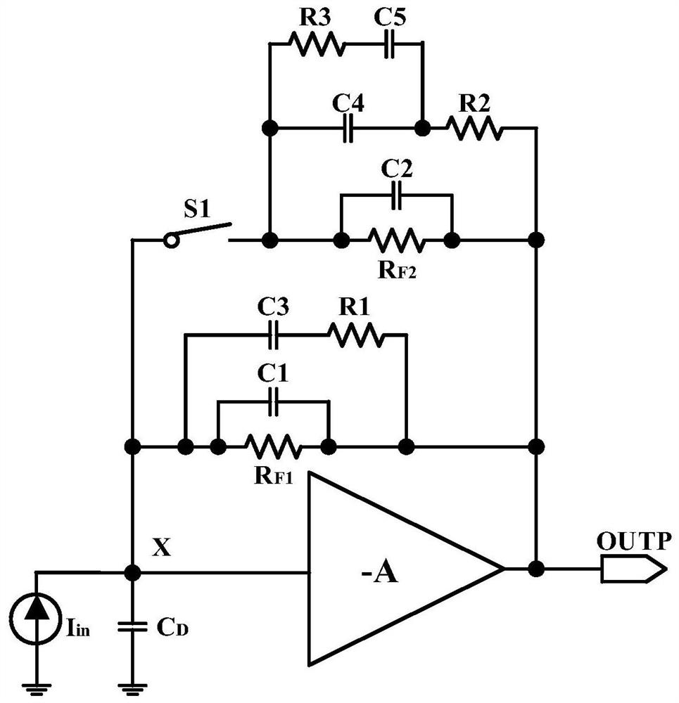
[0053] Specific implementation mode two: the following combination image 3 , Figure 5 and Figure 6 Describe this embodiment. The difference between this embodiment and Embodiment 1 is that in the transimpedance R F1 The two ends are further connected in parallel circuit structure: the resistor R3 and the capacitor C5 are connected in parallel at both ends of the capacitor C4 in series, and then connected in series with the resistor R2 and then connected in parallel at the trans-resistance R F1 both ends;

[0054] in transimpedance R F2 Further parallel circuit structure at both ends: Capacitor C3 and resistor R1 are connected in parallel in transresistance R F2 both ends;

[0055] The TIA bandwidth is constant before and after the switch S1 is closed by adjusting the size of the capacitors C1-C5.

[0056] ① When switch S1 is off:

[0057]

[0058] ②When switch S1 is closed:

[0059]

[0060] The design concept of the transfer function of this embodiment is con...

specific Embodiment approach 3

[0064] Specific implementation mode three: the following combination Figure 4 Describe this embodiment. The difference between this embodiment and Embodiment 1 or 2 is that it also includes a frequency compensation structure, which includes PMOS transistors MP1-MP4, NMOS transistors MN1-MN3, resistors R4-R5 and capacitors C6~C7;

[0065] The gate of the PMOS transistor MP3 and the gate of the PMOS transistor MP4 are simultaneously connected to the bias voltage input terminal VB, and the source of the PMOS transistor MP3 and the source of the PMOS transistor MP4 are simultaneously connected to the power supply VCC;

[0066] The gate of the PMOS transistor MP1 is connected to the signal input terminal VN, the source of the PMOS transistor MP1 and the source of the PMOS transistor MP2 are simultaneously connected to the drain of the PMOS transistor MP3; the drain of the PMOS transistor MP1 is simultaneously connected to the drain and gate of the NMOS transistor MN1 electrode an...


PUM


Abstract

The invention discloses a multi-transimpedance constant-bandwidth ultralow-noise TIA, belongs to the technical field of optical communication chips, and aims to solve the problems that the sensitivityand the linearity of an output signal are influenced and the overall performance of the TIA cannot be ensured due to large bandwidth and noise change of a common selectable transimpedance TIA. A capacitor C1 is connected to the two ends of a trans-resistor RF1 in parallel, a capacitor C2 is connected to the two ends of a trans-resistor RF2 in parallel, and the sizes of the capacitor C1 and the capacitor C2 are adjusted to meet the requirement that the TIA bandwidth is constant before and after a switch S1 is closed. The two ends of the trans-resistor RF1 are further connected with a circuit structure in parallel. A resistor R3 and a capacitor C5 are connected in series and then connected to the two ends of a capacitor C4 in parallel and then connected with a resistor R2 in series and thenconnected to the two ends of the trans-resistor RF1 in parallel. The two ends of the trans-resistor RF2 are further connected with a circuit structure in parallel. A capacitor C3 and a resistor R1 are connected in series and then connected to the two ends of the trans-resistor RF2 in parallel. The TIA bandwidth is constant before and after the switch S1 is closed by adjusting the capacitors C1-C5.

Description

technical field [0001] The invention belongs to the technical field of optical communication chips, and relates to a technique for keeping a constant bandwidth of a transimpedance amplifier TIA with multiple transimpedances during transimpedance and transimpedance switching. Background technique [0002] At the receiving end of the optical fiber communication integrated circuit, it is necessary to convert the optical signal into a current signal through a photodiode (PD), and then convert the current signal into a voltage signal through a transimpedance amplifier (TIA). Inside the linear TIA chip, it is usually designed as a multi-transimpedance mode to improve the dynamic range of the TIA to meet the requirements of various application scenarios. However, the change of the transimpedance value will inevitably greatly change the overall bandwidth of the chip, and the input equivalent noise will also deteriorate, which cannot meet the demanding requirements of the application...

Claims


Application Information

Patent Timeline
Patent Type & Authority Applications(China)
IPC IPC(8): H03F1/26
CPCH03F1/26Y02D30/70
Inventor 李景虎于建海涂航辉
Owner QIANDU TONGCHIP XIAMEN MICROELECTRONICS TECH CO LTD
Why Eureka
Try Eureka