Design method for weak magnetic controller of induction motor based on simplification of voltage loop structure
A technology for induction motors and magnetic controllers, applied in motor generator control, electronically commutated motor control, electromechanical brake control, etc., can solve problems such as system oscillation and instability, and achieve reduced current ripple and voltage loop bandwidth Constant, avoiding the effect of system shock or even instability
- Summary
- Abstract
- Description
- Claims
- Application Information
AI Technical Summary
Problems solved by technology
Method used
Image
Examples
specific Embodiment approach 1
[0029] Specific Embodiment 1: The design method of the induction motor field weakening controller based on the simplification of the voltage loop structure described in this embodiment, the method includes the following steps:
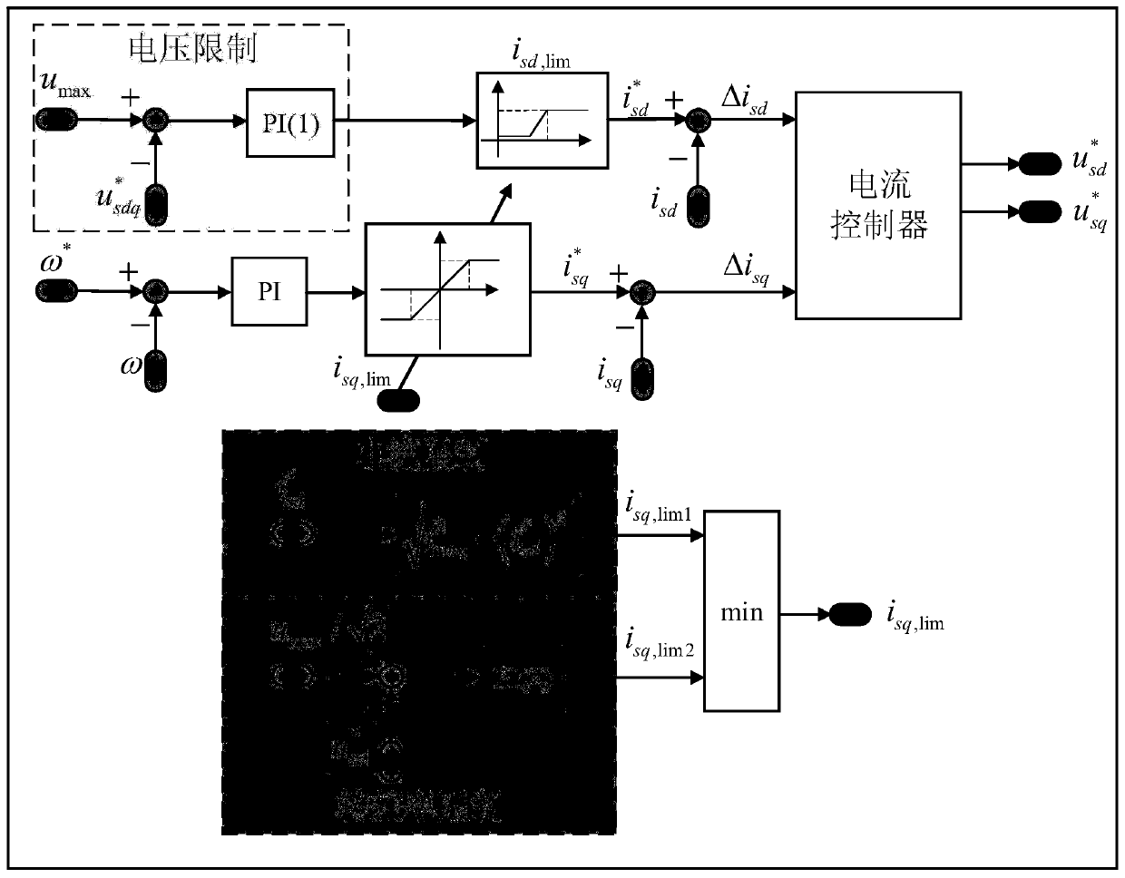
[0030] Step 1. Resetting the voltage reference and voltage feedback in the induction motor field weakening control model based on voltage closed loop; according to the reset voltage reference and voltage feedback, an improved induction motor field weakening control model based on voltage closed loop is obtained;
[0031] In the improved field-weakening control model of induction motor based on voltage closed-loop, the influence of q-axis voltage command u is analyzed sq * signal to obtain the structural model of the voltage closed loop I;
[0032] In the improved field-weakening control model of induction motors based on voltage closed-loop, the analysis of the influence of the d-axis voltage command u sd * The signal of the voltage closed-loop II s...
specific Embodiment approach 2
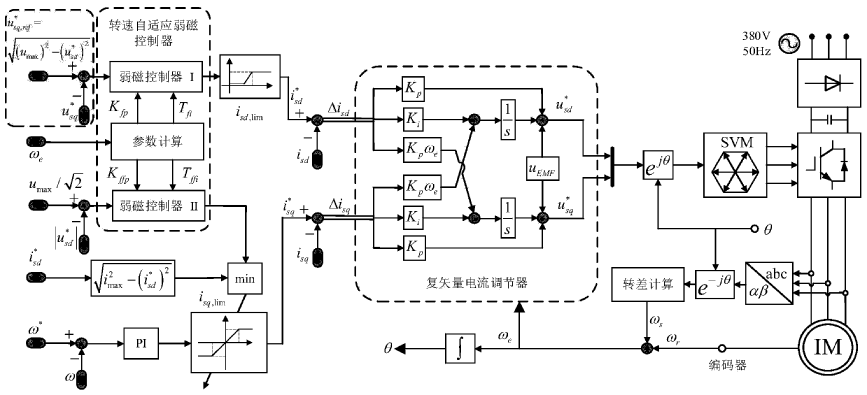
[0061] Embodiment 2: The difference between this embodiment and Embodiment 1 is that: the voltage setting and voltage feedback in the induction motor flux-weakening control model based on the voltage closed loop are reset; according to the reset voltage setting and voltage feedback , to obtain an improved induction motor flux-weakening control model based on voltage closed-loop, which is specifically:
[0062] Reset the voltage reference of the induction motor field weakening control model based on the voltage closed loop to u sq,ref * ,in: where u sq,ref * is the given field weakening voltage, u sd * is the d-axis voltage command output by the complex vector current regulator, u max It is given for the original excitation voltage of the induction motor field weakening control model based on the voltage closed loop, that is, the maximum voltage value allowed by the system operation;
[0063] Resetting the voltage feedback for the voltage closed-loop based induction mot...
specific Embodiment approach 3
[0069] Embodiment 3: The difference between this embodiment and Embodiment 1 or 2 is that in Step 1, in the improved induction motor flux-weakening control model based on voltage closed-loop, the influence of the q-axis voltage command u is analyzed. sq * signal to obtain the structural model of the voltage closed-loop I; in the improved induction motor flux-weakening control model based on the voltage closed-loop, analyze the influence of the d-axis voltage command u sd * The signal of the voltage closed-loop II structure model is obtained; specifically:
[0070] In the improved induction motor field weakening control model based on voltage closed loop, such as image 3 As shown, the analysis affects the output voltage command signal u of the complex vector current regulator sq * There are: Back EMF term u sq,EMF , d-axis current error Δi sd Through the coupling term of the complex vector current regulator, the q-axis current error Δi sq Through the proportional-integr...
PUM
 Abstract
Description
Claims
Application Information
 - R&D
- Intellectual Property
- Life Sciences
- Materials
- Tech Scout
- Unparalleled Data Quality
- Higher Quality Content
- 60% Fewer Hallucinations
Browse by: Latest US Patents, China's latest patents, Technical Efficacy Thesaurus, Application Domain, Technology Topic, Popular Technical Reports.
© 2025 PatSnap. All rights reserved.Legal|Privacy policy|Modern Slavery Act Transparency Statement|Sitemap|About US| Contact US: help@patsnap.com


