Eureka AIR delivers breakthrough ideas for toughest innovation challenges, trusted by R&D personnel around the world.

Voltage source converter based high voltage direct current transmission additional constant-capacity damping control method

A high-voltage direct current transmission and damping control technology, which is applied in the direction of power transmission AC network, electrical components, circuit devices, etc., can solve the problem of not making full use of the modulation capability of voltage source converters, insufficient output, parameter coordination, and small modulation quantities, etc. problem, to achieve the effect of no need for parameter coordination optimization, stable operation, and simple parameter design

Active Publication Date: 2017-06-20
SICHUAN UNIV
View PDF3 Cites 1 Cited by
  • Summary
  • Abstract
  • Description
  • Claims
  • Application Information

AI Technical Summary

Problems solved by technology

[0003] At present, the commonly used HVDC additional damping control method mostly uses the active power modulation of the voltage source converter to design the additional controller, which does not fully utilize the modulation capability of the voltage source converter.
However, the transmission capacity of the voltage source converter is still small, so the modulation amount for active power participation modulation is small, and the disturbance caused by serious faults will appear to be insufficient and the coordination of parameters is more complicated.

Method used


Image

  • Voltage source converter based high voltage direct current transmission additional constant-capacity damping control method
  • Voltage source converter based high voltage direct current transmission additional constant-capacity damping control method
  • Voltage source converter based high voltage direct current transmission additional constant-capacity damping control method

Examples


Embodiment Construction

[0040] The present invention will be further described in detail below in conjunction with the accompanying drawings and specific embodiments. Analyze and model the transient energy of system oscillation, start from the consumption mechanism of system transient energy, find the relationship between transient energy consumption and power modulation, and design a constant-capacity damping controller. The control method of controller of the present invention comprises the following steps:

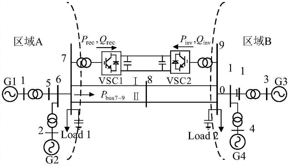
[0041] Step 1. Simulate the system to detect the inertia center speed difference signal of the generators in the two regions under the condition of no disturbance; add a step disturbance of 0.02 times p.u. to the active power setting value of the converter station, and then detect the generators in the two regions The rotational speed difference signal of the center of inertia; the measured rotational speed difference minus the rotational speed difference under the condition of no disturbance ...


PUM


Abstract

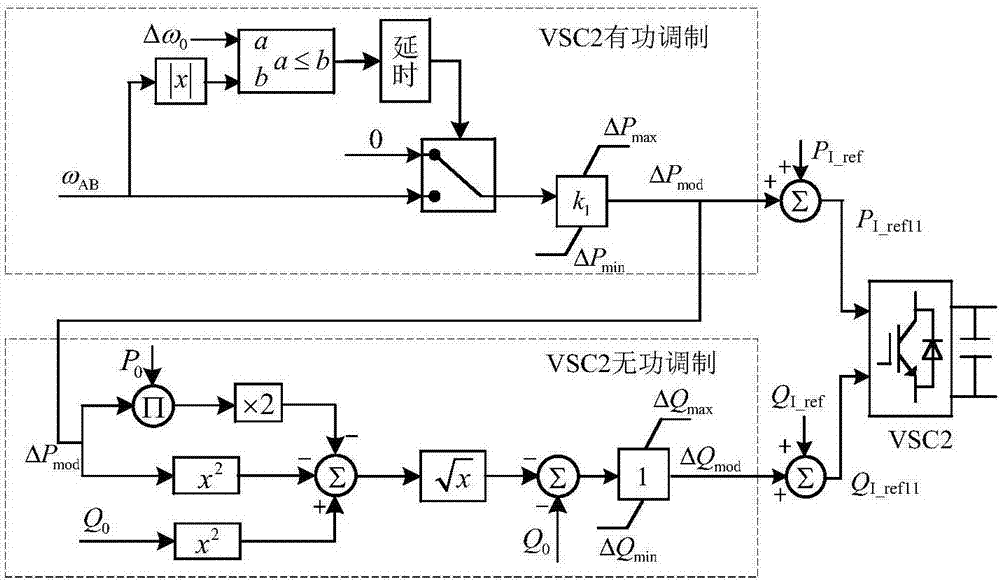
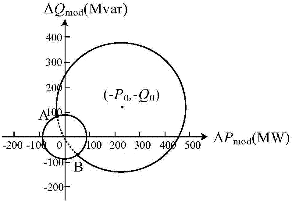
The invention discloses a voltage source converter based high voltage direct current transmission additional constant-capacity damping control method, which comprises the steps of performing oscillation characteristic identification on a system, and determining a low-frequency oscillation mode required to be suppressed; detecting a speed difference signal OmegaAB of inertia centers of two regional generators, enabling the speed difference signal OmegaAB to act as an input signal of a controller, performing amplification and amplitude limiting on the speed difference signal OmegaAB through a gain link so as to act as an active additional modulation signal deltaPmod, superposing the active additional modulation signal deltaPmod and an original active setting value PI_ref to act a new active setting value PI_ref11; enabling the active modulation signal to act as input of a reactive modulation link, acquiring a reactive modulation signal Qmod through a mathematical logic link, and superposing the passive modulation signal Qmod and an original active setting value QI_ref to act as a new active setting value QI_ref11. The method disclosed by the invention ensures the transmission capacity of a converter station to be constant, thereby being conducive to stable running of the system; and the control law derived through a mathematical method does not depend on a specific system model, thereby having excellent transportability.

Description

technical field [0001] The invention belongs to the field of high-voltage direct current transmission, in particular to a high-voltage direct current damping control method for a voltage source type converter that maintains a constant transmission capacity of the converter based on the principle of transient energy. Background technique [0002] With the increasing scale of the power grid and the access of DC transmission, my country has formed an AC-DC regional interconnected power system, and the impact of low-frequency oscillation on stability is more and more worthy of attention. In view of the advantages of voltage source converter based high voltage direct current transmission (VSC-HVDC) active and reactive fast independent decoupling control, it is becoming more and more important to use its additional control to suppress low-frequency oscillations in power systems. The more practical it is. [0003] At present, the commonly used HVDC additional damping control metho...

Claims


Application Information

Patent Timeline
Patent Type & Authority Applications(China)
IPC IPC(8): H02J3/24H02J3/36
CPCY02E60/60H02J3/24H02J3/36H02J2003/365
Inventor 张英敏蒋容刘天琪刘凯曾琦杨林李志晗邓旗
Owner SICHUAN UNIV
Why Eureka
Eureka Blog
Learn More