Discharge circuit and discharge control method

A technology of discharge control and discharge resistance, which is applied in the direction of battery circuit devices, circuits, circuit devices, etc., can solve the problems of inability to realize active discharge at the output end, increase the complexity of module design, and affect system functions, so as to avoid heat accumulation and reduce Device cost, effects of extended application range

Active Publication Date: 2017-06-20
XIAN TGOOD INTELLIGENT CHARGING TECH CO LTD
View PDF7 Cites 4 Cited by
  • Summary
  • Abstract
  • Description
  • Claims
  • Application Information

AI Technical Summary

Problems solved by technology

[0008] (1) In order to make the discharge resistor R1 withstand the heat accumulation generated by the instantaneous large current, it is necessary to choose a high-power resistor device, which means choosing a high-cost and large-volume power resistor, and even the air duct design must be Taking the discharge resistor into consideration indirectly increases the complexity of the module design;
[0009] (2) The output discharge is controlled by the hardware discharge enable signal, and the discharge action is only performed when the module is separated from the system, and the active discharge at the output end of the charging system cannot be realized, which affects the system function

Method used


Image

  • Discharge circuit and discharge control method
  • Discharge circuit and discharge control method
  • Discharge circuit and discharge control method

Examples


Embodiment Construction

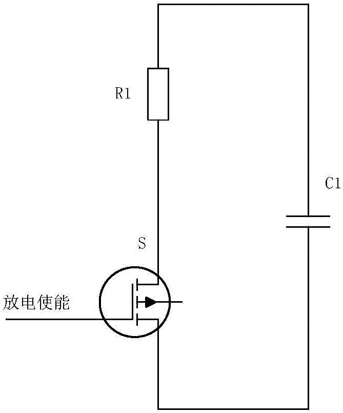
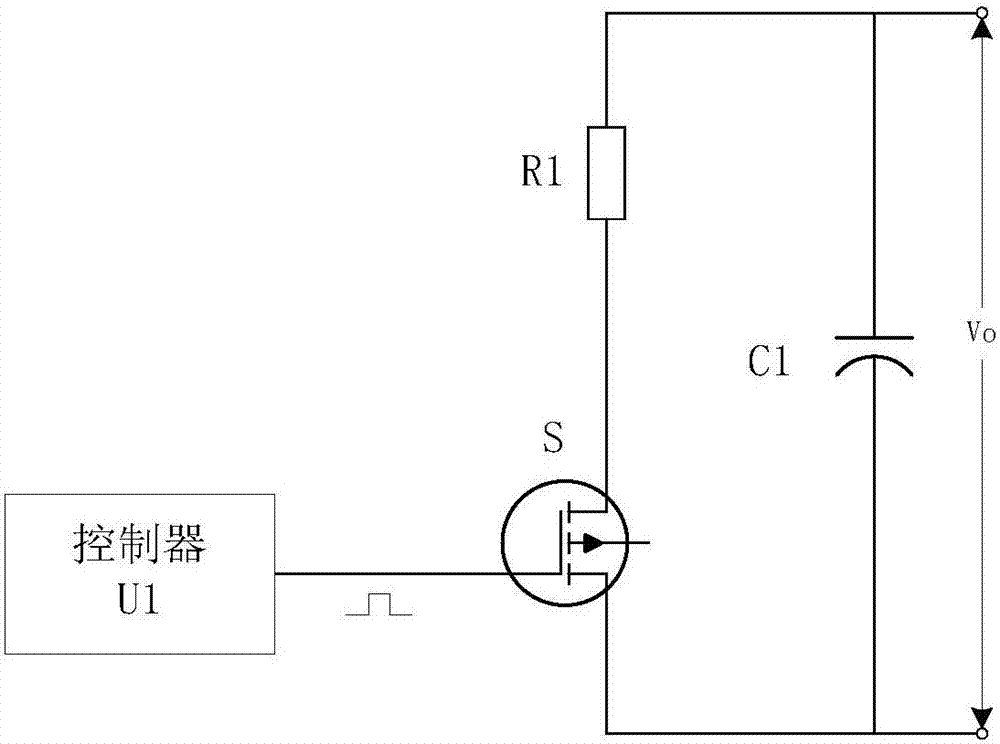
[0070] figure 2 It is a circuit diagram of Embodiment 1 of the output port filter capacitor and discharge circuit of the present invention. The DC charging module of this embodiment includes a voltage conversion circuit (not shown), a filter capacitor C1 and a discharge circuit, wherein the voltage conversion circuit is used to convert the AC market The electricity is converted into direct current and provides power for electric vehicles. The filter capacitor C1 is set at the output port of the DC charging module, and is used to reduce the ripple of the output voltage. The discharge circuit includes a discharge resistor R1, a switch tube S and a controller U1. Among them, the discharge resistor R1 preferably has a power resistor with a certain impact resistance, and the first end of the discharge resistor R1 is connected to the first end of the filter capacitor C1, and the second end of the discharge resistor R1 is connected to the first end of the switch tube S , the secon...


PUM


Abstract

The invention relates to a discharge circuit and a discharge control method. The discharge control method comprises the following steps: judging whether discharge conditions are met, if yes, when each discharge period is started, acquiring the initial discharge voltage of the current discharge period, and judging whether the initial discharge voltage of the current discharge period is greater than preset voltage, if yes, generating a pulse signal of the current discharge period according to the initial discharge voltage of the current discharge period, wherein the generated pulse signal enables the discharge energy of a discharge resistor in effective pulse discharge time and the average power of the discharge resistor in the discharge periods to meet the derating requirement of the discharge resistor; outputting the pulse signal to a switch tube so as to control the on and off of the switch tube, and realizing the discharge function of the current discharge period. By implementing the technical scheme of the invention, the discharge time can be effectively shortened while reliable discharge of the discharge circuit of a direct-current charge module is guaranteed, and meanwhile the selection range of the discharge resistor is enlarged, so that the cost of the device is reduced.

Description

technical field [0001] The invention relates to the field of DC charging, in particular to a discharge circuit and a discharge control method. Background technique [0002] In the intelligent group charging system, a large number of DC charging modules are equipped to realize the conversion of AC input to DC and provide electric energy for charging electric vehicles. According to the requirements of the national standard, the upper limit of the output voltage of some DC charging modules is relatively high, usually up to 750V. In order to reduce the output ripple, the DC charging module generally configures a filter capacitor with a certain capacity at its output port. However, the filter capacitor makes the self-discharge speed of the port voltage very slow when the output high voltage is turned off with no load, which affects the application of the DC charging module in the intelligent charging system. It is necessary to design a special discharge circuit to complete the o...

Claims


Application Information

Patent Timeline
Patent Type & Authority Applications(China)
IPC IPC(8): H02J7/02H01M10/44
CPCH01M10/441H02J7/027Y02E60/10
Inventor 吕剑孙景沈得贵袁庆民茹永刚
Owner XIAN TGOOD INTELLIGENT CHARGING TECH CO LTD
Why Eureka
Try Eureka