Heating beater device

A technology of equipment and slurry cups, which is applied to utensils with integral electric heating devices, cooking utensils, household utensils, etc., can solve problems such as hot hands, unreasonable design, ignition, etc., and achieve the effect of stable coupling connection and simple structure improvement

Active Publication Date: 2017-06-23
佛山市顺德区康美来生活电器有限公司
View PDF10 Cites 2 Cited by
  • Summary
  • Abstract
  • Description
  • Claims
  • Application Information

AI Technical Summary

Problems solved by technology

The disadvantages of this coupling connection structure are: 1. The heating and beating equipment will generate a large amount of water vapor when it is working, and the water vapor is pervasive, and it will diffuse outward from the gap between the machine head and the cup body; The connection position of the connector is at the same level as the mouth of the cup, or even higher than the mouth of the cup. Therefore, when the water vapor diffuses upward, it will enter the coupling connection position, resulting in ignition or even electric leakage.
2. At present, the coupler generally plays the role of coupling power connection and fixing the machine head, but the machine head will vibrate violently and swing from side to side during the working process, and the impact force will cause the upper connector and the lower connector of the coupler to vibrate. If the connection becomes loose, over time, not only will it not be able to fix the machine head well, but also water vapor will more easily enter the coupling connection position, causing water leakage, electric leakage, etc.
However, the design of this structure is unreasonable. When the user uses the handle to lift the machine head, the water vapor will entrain the condensed water and flow down through the vent hole, directly falling on the user's hand, which will inevitably cause hot hands. There are security risks
[0004] Not only that, the circuit board of the existing heating and beating equipment is generally arranged on the motor and installed on the machine head together. The defect of this design is that the control circuit is prone to electromagnetic interference during the operation of the motor, and the circuit board is exposed to high temperature for a long time. In hot and humid environment, problems such as electric leakage and damage are prone to occur

Method used


Image

  • Heating beater device
  • Heating beater device
  • Heating beater device

Examples


Embodiment Construction

[0038] The technical solution will be described in detail below in conjunction with specific embodiments.

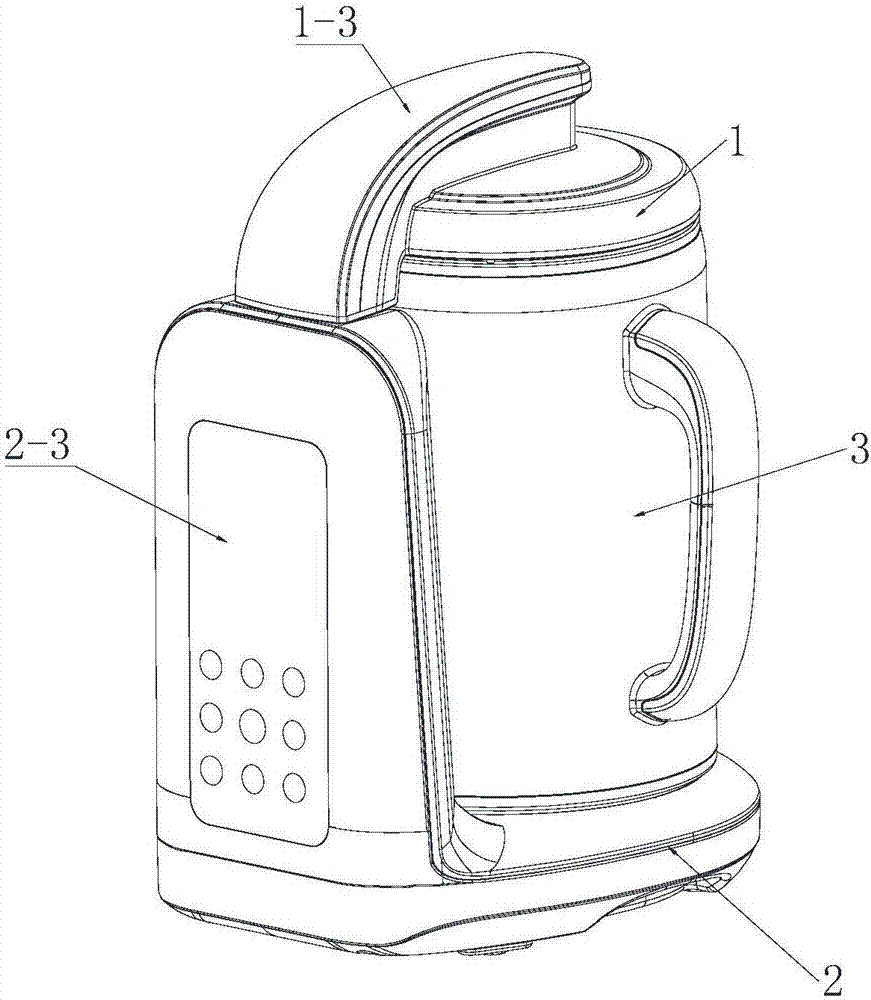
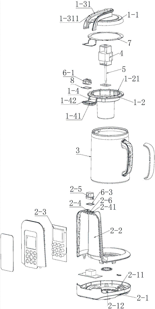
[0039] Such as Figure 1-Figure 5As shown, the present invention is a kind of heating and beating equipment, including a machine head 1, a base 2 and a beating cup body 3, the beating cup body is placed on the base, the machine head and the beating cup body are connected and matched, and the machine head 1 includes a machine head cover 1 -1 and machine head base 1-2, motor assembly 4 is arranged in the machine head base, the motor assembly is connected with stirring rod 5, handle 1-3 is provided on the machine head cover, control circuit is provided in the base, machine The head and the base are connected through a coupler 6, and the control circuit is connected to the control motor assembly, so that the motor is separated from the control circuit; the coupler 6 includes upper and lower connectors 6-1, 6-2, and the coupling of the upper and lower connectors The height o...


PUM


Abstract

The invention discloses a heating beater device, comprising a head, a base and a beating cup body. The beating cup body is arranged on the base. The head is connected and matched with the beating cup body. The head comprises a head cover and a head seat. The head seat is internally provided with a motor assembly, which is connected with a stirrer. The head cover is provided with a handle. The heating beater device is characterized in that a control circuit is arranged in the base, the head and the base are connected by a coupler, the control circuit is connected with and controls the motor assembly to separate the motor from the control circuit, the coupler includes an upper connector and a lower connector, and the height of the coupling connection position of the upper connector and the lower connector is lower than the cup mouth level of the beating cup body. The heating beater device has the advantages of simple structure, reasonable design, better stability, safer use and longer service life compared with the same type of products.

Description

technical field [0001] The invention relates to the technical field of heating and beating equipment. Background technique [0002] Most of the heating and beating equipment currently on the market is composed of two parts: the machine head and the cup body. Usually, the power supply enters the heating and beating equipment from the cup body, so a connecting device is needed to realize the power supply from the cup body to the machine head. Inside. At present, the circuit connection between the cup body and the machine head on the market mostly uses a coupler to realize the connection between the two. The coupler generally includes two parts, an upper connector and a lower connector. In order to make production and processing more convenient, the connection positions of the upper and lower connectors are generally at the same level as the mouth of the cup, or even higher than the mouth of the cup. The disadvantages of this coupling connection structure are: 1. The heating ...

Claims


Application Information

Patent Timeline
Patent Type & Authority Applications(China)
IPC IPC(8): A47J27/00A47J43/07A47J43/08
CPCA47J27/004A47J43/0705A47J43/082
Inventor 黎进荣
Owner 佛山市顺德区康美来生活电器有限公司
Why Eureka
Try Eureka