Steel moving arm for moving and transporting cooling bed steel billet

A billet and cooling bed technology, applied in the field of steel moving arm, can solve the problems of shortening the transportation time of the steel moving arm and conveyor belt, occupying a large area, and setting up a separate motor for the steel moving arm, so as to shorten the transportation time, The effect of prolonging the service life and improving the transportation efficiency

Inactive Publication Date: 2017-06-23
CHENGDU METALLURGICAL EXPERIMENTAL PLANT
View PDF6 Cites 0 Cited by
  • Summary
  • Abstract
  • Description
  • Claims
  • Application Information

AI Technical Summary

Problems solved by technology

[0003] The object of the present invention is to provide a steel moving arm used for moving and transporting steel billets in a cooling bed, which solves the problem of requiring a separate motor for the steel moving arm when traditionally using the steel moving arm for transportation, resulting in a large footprint and shortening the The transportation time of the traditional shifting steel arm on the cooling bed's transportation teeth and conveyor belt is reduced

Method used


Image

  • Steel moving arm for moving and transporting cooling bed steel billet
  • Steel moving arm for moving and transporting cooling bed steel billet
  • Steel moving arm for moving and transporting cooling bed steel billet

Examples


Embodiment 1

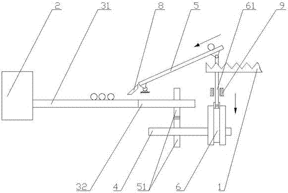
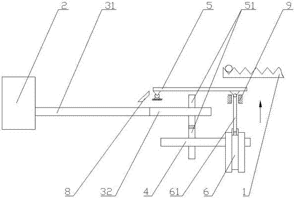
[0034] Such as figure 1 and 2 As shown, the moving steel arm used for the mobile transportation of the cooling bed billet includes a fixed frame, a motor 2, a transportation main shaft, a wheel shaft 4 and a steel arm main body 5, the motor 2 drives the transportation main shaft, and the transportation main shaft includes a conveying part 31 and a transmission part 32, The transmission part 32 of the wheel shaft 4 and the transport main shaft is provided with a gear 51, and the transport main shaft drives the wheel shaft 4 through the meshing of the gear 51. The wheel shaft 4 is also provided with a cam 6 located below the cooling bed 1, and the cam 6 is also equipped with a material Push rod 61; one end of the steel arm main body 5 is located above the conveying part 31, and is connected to the fixed frame by a hinge, and the other end is hingedly connected with the material push rod 61; the cam 6, the material push rod 61 and the steel arm main body 5 constitute With the ca...

Embodiment 2

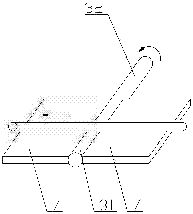
[0036] Such as figure 2 As shown, compared with Example 1, the present embodiment optimizes the conveying part 31. Along the steel billet conveying direction, conveying support plates 7 are provided on both sides of the conveying part 31 of the conveying main shaft. In this embodiment, conveying The support plate 7 can further help the transport main shaft to transport the steel billet, preventing the steel billet from falling from the transport support plate 7.

Embodiment 3

[0038] Such as figure 1 and 2 As shown, compared with Example 2, this embodiment adds a buffer swash plate 8, and between one end of the steel arm main body 5 and the transport support plate 7, a buffer swash plate 8 for buffering the steel billet to slide down is also provided, and one end of the buffer swash plate 8 It is connected with one end of the steel arm main body 5, one end is located on the transport support plate 7, and the other end is arranged at the blanking end of the steel arm main body 5 along the moving direction of the steel billet. When the main body 5 slides and falls, it falls on the transport support plate 7, reducing the impact force of the steel billet, thereby protecting the conveying part 31 and the transport support plate 7 on the transport main shaft, thereby prolonging the service life.


PUM


Abstract

The invention discloses a steel moving arm for moving and transporting a cooling bed steel billet. The steel moving arm comprises a fixed bracket, a motor, a transporting main shaft, a wheel axle and a steel arm main body; the transporting main shaft is driven by the motor; the transporting main shaft comprises a conveying part and a transmission part; the transporting main shaft drives the wheel axle through the engagement of a gear; a cam is also arranged on the wheel axle; a material pushing rod is also mounted on the cam; one end of the steel arm main body is positioned above a conveying part; the other end of the steel arm main body is in hinged connection with the material pushing rod; the cam, the material pushing rod and the steel arm main body form a cam mechanism. The steel moving arm for moving and transporting the cooling bed steel billet has the beneficial effects that overlarge occupied area caused by arranging the motor on the conventional steel moving arm additionally is avoided by driving the steel moving arm to move through the transporting main shaft, and meanwhile, the transporting time is shortened; therefore, the transporting efficiency is improved.

Description

technical field [0001] The invention relates to a steel moving arm, in particular to a steel moving arm used for moving and transporting a cooling bed billet. Background technique [0002] When the traditional cooling bed moves the steel billet to the conveyor belt, it is often necessary to set up an additional motor to control the movement of the steel moving arm, which will cause the problem of too large area of ​​the site, and because the steel moving arm is driven by a chain, and Its journey is long, and the moving time is too slow, which reduces the transportation time of the entire transportation, thereby reducing work efficiency. Contents of the invention [0003] The object of the present invention is to provide a steel-moving arm used for moving and transporting steel slabs in a cooling bed, which solves the problem that an additional motor needs to be provided for the steel-moving arm when the traditional steel-moving arm is used for transportation, resulting...

Claims


Application Information

Patent Timeline
Patent Type & Authority Applications(China)
IPC IPC(8): B21B43/00
CPCB21B43/006
Inventor 周志梭
Owner CHENGDU METALLURGICAL EXPERIMENTAL PLANT
Why Eureka
Try Eureka