
Micro motor shaft

A micro-motor and rotating shaft technology, applied in shafts, couplings, shafts and bearings, etc., can solve problems such as inability to continue working, and achieve the effects of increasing life, improving safety, and avoiding breakage

Inactive Publication Date: 2017-06-23
CHONGQING TONGJIA ELECTRONICS TECH CO LTD
View PDF0 Cites 0 Cited by
  • Summary
  • Abstract
  • Description
  • Claims
  • Application Information

AI Technical Summary

Problems solved by technology

After the shaft breaks, the power output is completely interrupted and cannot continue to work

Method used


Image

  • Micro motor shaft
  • Micro motor shaft

Examples


Embodiment 1

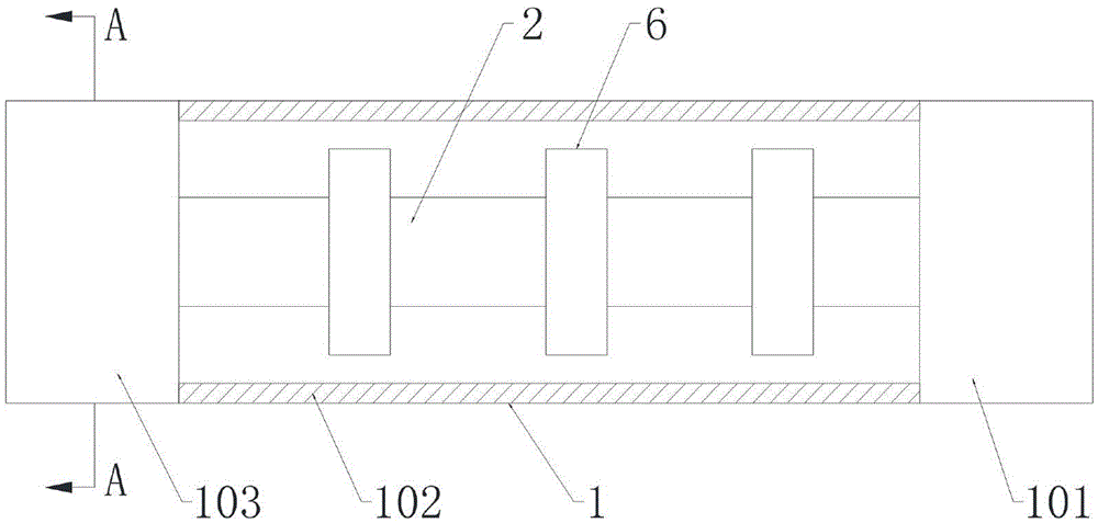
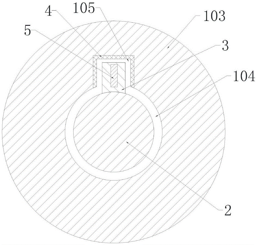
[0021] like figure 1 and figure 2 As shown, the rotating shaft of the micro-motor includes a rotating shaft 1 and an inner shaft 2; the rotating shaft body 1 includes an input section 101, a connecting cylinder 102 and a transmission section 103, and the two ends of the connecting cylinder 102 are respectively connected with the input section 101 and the transmission section 103, and the transmission section 103 is provided with a circular accommodation hole 104 and a square transmission hole 105 at one end close to the connecting cylinder 102, the square transmission hole 105 communicates with the circular accommodation hole 104; the inner shaft 2 is located in the connecting cylinder 102, and the inner shaft 2 includes a first end and the second end, the first end of the inner shaft 2 is connected with the input section 101, the second end of the inner shaft 2 is located in the circular accommodation hole 104, and the outer surface of the second end of the inner shaft 2 is ...

Embodiment 2

[0024] like figure 1 and figure 2 As shown, on the basis of Embodiment 1, this embodiment further includes a rubber layer 4 disposed on the inner wall of the square transmission hole 105 .

[0025] The rubber layer 4 is provided to act as a buffer when the transmission block 3 collides with the inner wall of the square transmission hole 105, so as to prevent the transmission block 3 from breaking and improve the reliability of the rotating shaft.

Embodiment 3

[0027] like figure 1 and figure 2 As shown, on the basis of Embodiment 1, this embodiment further includes a magnet block 5 arranged in the transmission block 3 .

[0028] The magnet block 5 is set so that the transmission block 3 and the inner wall of the square transmission hole 105 are bonded together after the connecting cylinder 103 is broken, so that the transmission block 3 and the inner wall of the square transmission hole 105 are prevented from colliding again when the rotating speed is changed, and the life of the rotating shaft is improved.


PUM


Abstract

The invention discloses a micro-motor rotating shaft, which includes a rotating shaft and an inner shaft; the rotating shaft body includes an input section, a connecting cylinder and a transmission section, and one end of the transmission section close to the connecting cylinder is provided with a circular accommodation hole and a square transmission hole, and the square transmission hole It communicates with the circular accommodation hole; the inner shaft is located in the connecting cylinder, the inner shaft includes a first end and a second end, the first end of the inner shaft is connected with the input section, the second end of the inner shaft is located in the circular accommodation hole, and the inner shaft The outer surface of the second end of the shaft is not in contact with the circular receiving hole, and the second end of the inner shaft is also provided with a transmission block, the transmission block is located in the square transmission hole, and there is a gap between the outer surface of the transmission block and the inner wall of the square transmission hole ; The input section, the connecting cylinder, the transmission section, the circular accommodating hole and the inner shaft are coaxial; there is a gap between the inner shaft and the connecting cylinder. The present invention is provided with two sets of torque transmission components, the inner shaft and the connecting cylinder, and the torque is transmitted by the inner shaft after the connecting cylinder breaks and fails, so as to avoid the complete interruption of power output.

Description

technical field [0001] The invention relates to the field of motors, in particular to a rotating shaft of a micro-motor. Background technique [0002] Micro motor is a commonly used power output device, and its power is output through the rotating shaft. During the working process, the rotating shaft will bear a large torque, especially when the working load changes suddenly, the rotating shaft is very easy to break. After the shaft breaks, the power output is completely interrupted and cannot continue to work. Contents of the invention [0003] The purpose of the present invention is to overcome the deficiencies of the prior art and provide a micro-motor shaft suitable for occasions with many sudden changes in the working load. The shaft provides two transmission structures. After one of the transmission structures fails, the other transmission Structural work, to avoid the situation that the power output is completely interrupted. [0004] The object of the present in...

Claims


Application Information

Patent Timeline
IPC IPC(8): F16C3/02F16D9/00F16D3/02F16D3/14
CPCF16C3/02F16D3/02F16D3/14F16D9/00
Inventor 房锦山
Owner CHONGQING TONGJIA ELECTRONICS TECH CO LTD
Features
  • Generate Ideas
  • Intellectual Property
  • Life Sciences
  • Materials
  • Tech Scout
  • Unparalleled Data Quality
  • Higher Quality Content
  • 60% Fewer Hallucinations
Learn More