Centrifugal clutch structure

A centrifugal and clutch technology, which is applied in the field of clutches, can solve problems such as limited friction between shoe blocks and driven parts, and achieve the effects of eliminating gaps, improving life, and fixing and stabilizing

Inactive Publication Date: 2017-06-23
CHONGQING CHANGAN CLUTCH MFG
View PDF1 Cites 5 Cited by
  • Summary
  • Abstract
  • Description
  • Claims
  • Application Information

AI Technical Summary

Problems solved by technology

The problem with the existing centrifugal clutch structure is that the two ends of the two shoes are connected by spring

Method used


Image

  • Centrifugal clutch structure
  • Centrifugal clutch structure

Examples


Example Embodiment

[0031] Example 1:

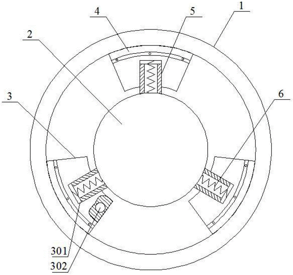
[0032] like figure 1 As shown, the centrifugal clutch structure includes a clutch housing 1, a runner 2, a shoe block 3, a friction plate 4, a guide cylinder 5 and a spring 6; the runner 2 is arranged in the clutch housing 1, and the runner 2 and the clutch housing 1 The shaft, the runner 2 is evenly provided with at least three guide cylinders 5 in the radial direction, the number of the shoe blocks 3 is the same as that of the guide cylinders 5, the shoe block 3 is provided with a guide hole 301, and the guide hole 301 slides with the guide cylinder 5. 6 is arranged in the guide cylinder 5, one end of the spring 6 is connected with the runner 2, the other end of the spring 6 is connected with the shoe block 3, the friction plate 4 is fixed on the outer surface of the shoe block 3; the outer diameter of the friction plate 4 is connected with the clutch The inner diameter of the shell 1 is the same; the shoe block 3 is provided with a accommodating cavity ...

Example Embodiment

[0035] Example 2:

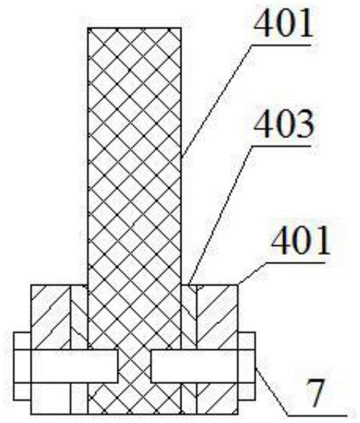
[0036] like figure 1 and figure 2 As shown, this embodiment is based on Embodiment 1. The friction plate 4 includes a connecting plate 401 fixed on the outer circular surface of the shoe block 3 and a friction portion 402 fixed on the connecting plate 401. The friction portion 402 The outer diameter of the friction part 402 is larger than the outer diameter of the connecting piece 401 , and the outer diameter of the friction part 402 is the same as the inner diameter of the clutch housing 1 .

[0037] During operation, the friction plate 4 is used to rub against the clutch housing 1, and the friction plate 4 is damaged quickly and needs to be replaced regularly. In order to facilitate the replacement of the friction plate 4, the friction plate 4 includes a connecting plate 401 fixed on the outer circular surface of the shoe block 3 and a friction part 402 fixed on the connecting plate 401. During operation, the friction part 402 rubs against the clutch h...

Example Embodiment

[0038] Example 3:

[0039] like figure 1 and figure 2 As shown, on the basis of Embodiment 2, the friction part 402 and the connecting piece 401 are connected by bolts 7 in this embodiment.


PUM


Abstract

The invention discloses a centrifugal clutch structure. The centrifugal clutch structure comprises a clutch housing, a rotating wheel, shoe blocks, friction pieces, guide cylinders and springs. The rotating wheel is arranged in the clutch housing. The rotating wheel and the clutch housing are arranged on the same axis. The rotating wheel is uniformly provided with the at least three guide cylinders. The number of the shoe blocks is equal to that of the guide cylinders. Guide holes are arranged in the shoe blocks. The guide holes and the guide cylinders are slidably matched. The springs are arranged in the guide cylinders. One end of each spring is connected with the rotating wheel and the other end of each spring is connected with one shoe block. The friction pieces are fixed on the outer circular surfaces of the shoe blocks. The outer diameters of the friction pieces are the same as the inner diameter of the clutch housing. An accommodating cavity is arranged in each shoe block and filled with water. The springs are arranged in the guide cylinders. Each shoe block corresponds to a spring so that multiple shoe blocks can be arranged on the rotating wheels. Therefore, the number of the shoe blocks can be adjusted according to friction force provided according to the need. The centrifugal clutch structure helps the temperature of the friction prices from rising too fast.

Description

technical field [0001] The invention relates to a clutch. Background technique [0002] Centrifugal clutch transmits torque through friction, and its basic structure consists of three elements: driving part, centrifugal body and driven part. The centrifuge is slipped on the active part, and the prime mover drives the active part to rotate and accelerate to throw it out in the radial direction. When the driving part reaches the specified angular velocity, the thrown out centrifugal body is pressed against the inner wall of the driven part, and is forced into a motion state by friction force to transmit torque. [0003] In the existing centrifugal clutch structure, such as the clutch disclosed in the invention patent application number 201410498467, the centrifugal body includes two shoes, and the two ends of the two shoes are connected by springs. The pulling force pulls the shoe back, separating the shoe from the follower. The problem with the existing centrifugal clutch ...

Claims


Application Information

Patent Timeline
IPC IPC(8): F16D43/14
CPCF16D43/14F16D2043/145F16D43/18
Inventor 谢惠
Owner CHONGQING CHANGAN CLUTCH MFG
Why Eureka
Try Eureka