Temperature sensing reversing valve

A reversing valve and inductive technology, applied in the field of temperature-sensing reversing valves, can solve the problems of weak adaptability to the use environment, high manufacturing cost, inconvenient installation, etc.

Active Publication Date: 2017-06-23
何振东
View PDF5 Cites 8 Cited by
  • Summary
  • Abstract
  • Description
  • Claims
  • Application Information

AI Technical Summary

Problems solved by technology

[0004] In order to solve the disadvantages of inconvenient use, complex structure, high manufacturing cost, inconvenient installation and weak adaptability to the use environment of the existing hot and cold water switching valves, the present invention provides a medium flow channel that can be automatically switched according to the temperature of the medium entering the valve. The temperature-sensing reversing valve includes a valve body, a temperature-sensing reversing valve core, a temperature-sensing switching assembly and a valve body blocking assembly; the valve body is provided with a medium inlet channel, a low-temperature medium outlet channel and a high-temperature medium outlet channel One end of the medium inlet channel, the low-temperature medium outlet channel and the high-temperature medium outlet channel are connected in the valve body; the temperature-sensitive reversing valve core is arranged in the valve body where the three channels communicate with each other The position is used to switch the medium flow channel between the low-temperature medium outlet channel and the high-temperature medium outlet channel; One end is used to switch the temperature-sensitive reversing valve core to enter the temperature-sensing mode or the non-temperature-sensing mode; the valve body blocking cover assembly is arranged on the valve body at one end of the high-temperature medium outlet channel

Method used


Image

  • Temperature sensing reversing valve
  • Temperature sensing reversing valve
  • Temperature sensing reversing valve

Examples


Embodiment 1

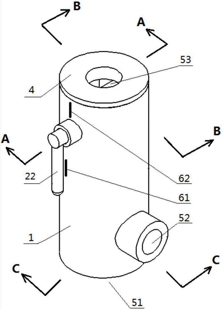
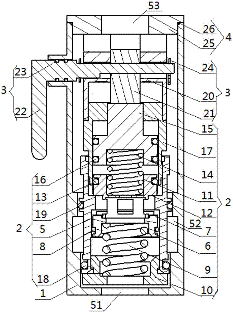
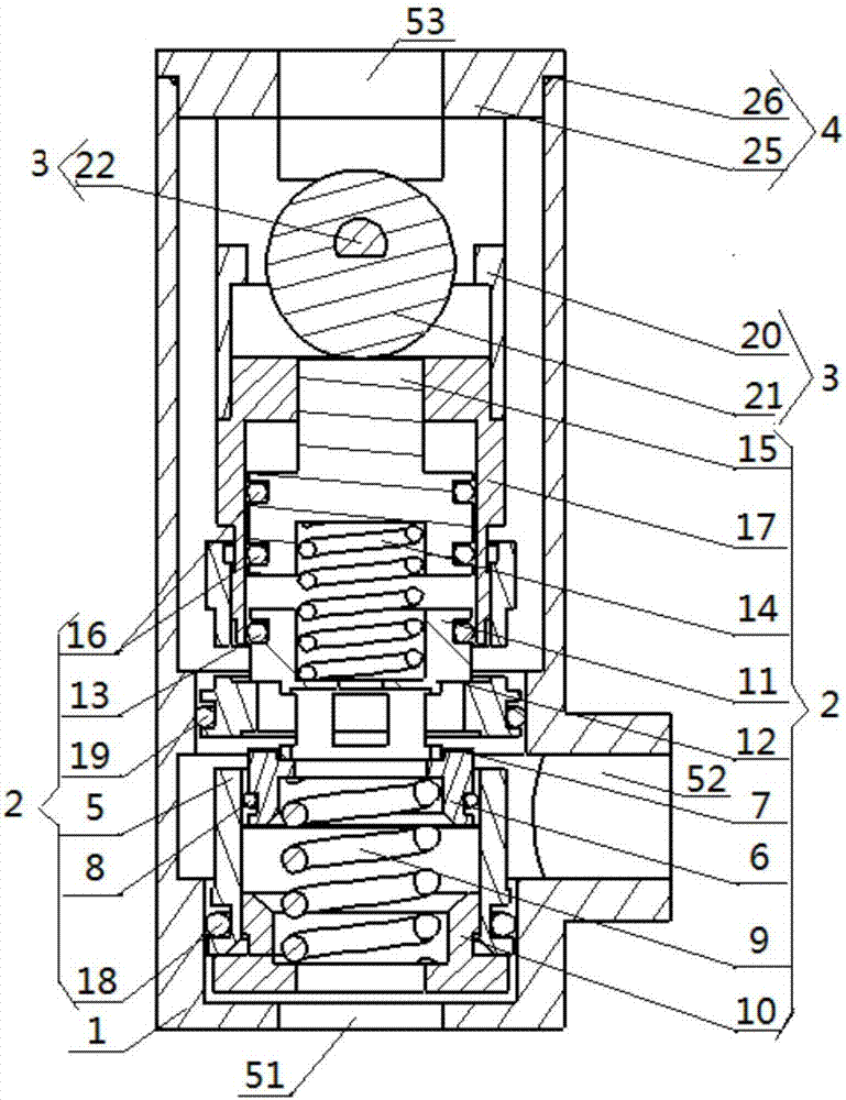
[0040] see Figure 1 to Figure 7 , this embodiment provides a temperature-sensing reversing valve, including a valve body 1 , a temperature-sensing reversing valve core 2 , a temperature-sensing switching assembly 3 and a valve body blocking assembly 4 . Among them, the valve body 1 is provided with a medium inlet channel 51, a low temperature medium outlet channel 52 and a high temperature medium outlet channel 53; one end of the medium inlet channel 51, the low temperature medium outlet channel 52 and the high temperature medium outlet channel 53 is inside the valve body Communication setting; the temperature-sensitive reversing spool 2 is set at the position where the three passages (medium inlet passage 51, low-temperature medium outlet passage 52 and high-temperature medium outlet passage 53) in the valve body 1 communicate with each other, and are used for the low-temperature medium outlet passage 52 switch between the medium flow channel and the high-temperature medium ...

Embodiment 2

[0048] The difference between the temperature-sensing reversing valve provided in this embodiment and the embodiment 1 lies in that the structure of the temperature-sensing reversing valve core is different. Other than that, other structures are the same as those in Embodiment 1, and will not be repeated in this embodiment.

[0049] see Figure 8 to Figure 10The temperature-sensitive reversing spool 2 of this embodiment includes a spool body 56, a spool c86, a sealing ring 8 for the spool a, a memory alloy spring 9, a blocking cover a10, a sealing ring 13 for the spool b, a spring b14, and a control cover 15. Control cover seal ring 16, plug cover b17, valve core body seal ring a18 and valve core body seal ring b19. Among them, the main body 56 of the spool is a tubular structure with a protruding step inside it, and the two sides of the step are respectively provided with a low-temperature medium outlet and a high-temperature medium outlet, and the inner cylindrical surface ...

Embodiment 3

[0054] The difference between the temperature-sensing reversing valve provided in this embodiment and the embodiment 1 is that it does not include a temperature-sensing switching component, the valve body is replaced by a small valve body, and the composition and structure of the temperature-sensing reversing valve core is different. Other than that, other structures are the same as those in Embodiment 1, and will not be repeated in this embodiment.

[0055] see Figure 11 and Figure 12 , the temperature-sensing reversing valve of this embodiment includes a small valve body 66 , a temperature-sensing reversing valve core 2 and a valve body plug assembly 4 . Among them, the small valve body 66 is provided with a medium inlet passage 51, a low temperature medium outlet passage 52 and a high temperature medium outlet passage 53; 66 internal communication setting; the temperature-sensitive reversing valve core 2 is set at the position where the three channels in the small valve...


PUM


Abstract

The invention discloses a temperature sensing reversing valve, which belongs to the technical field of valves. The reversing valve comprises a valve body, a temperature sensing reversing valve element, a temperature sensing switching component and a valve body blanking cover component; the valve body is provided with a medium inlet passage, a low temperature medium outlet passage and a high temperature medium outlet passage; certain ends of the medium inlet passage, the low temperature medium outlet passage and the high temperature medium outlet passage are communicated in the valve body; the temperature sensing reversing valve element is in the communicating position of the three passages in the valve body; the temperature sensing switching component is disposed on one end of the temperature sensing reversing valve element higher than the high temperature medium outlet passage; the valve body blanking cover component is arranged on one end of the valve body higher than the high temperature medium outlet passage. The invention further provides another temperature sensing reversing valve. The invention can realize a temperature sensing working mode and a non temperature sensing working mode, and has the advantages of simple structure, low manufacturing cost, convenient to mount and use and wide in the range of applicable occasions and the like, the appearance is of a cylindrical tee structure and water resource is saved.

Description

technical field [0001] The invention relates to the technical field of valves, in particular to a temperature-sensing reversing valve for automatically switching medium flow channels according to the temperature of the medium entering the valve. Background technique [0002] Modern homes, hotels or schools are all equipped with domestic hot water supply systems. The hot water supply system transports hot water to the hot water use end through the conduit; when the hot water use end does not use hot water for a long time, the water temperature in the conduit and the temperature of the conduit will cool down to below the ideal temperature; When using water, it is necessary to release the cold water in the conduit first, and the hot water will only flow out after the conduit is heated by the hot water. The following problems will occur in this way: 1) the user must constantly feel and judge the water temperature when releasing the water, which is inconvenient to use; 2) if the...

Claims


Application Information

Patent Timeline
Patent Type & Authority Applications(China)
IPC IPC(8): F16K11/20F16K31/70F16K27/04F16K3/314
CPCF16K3/314F16K11/20F16K27/041F16K31/002
Inventor 何振东
Owner 何振东
Why Eureka
Try Eureka