
Power Transfer Circuit And Method Utilizing Power Capability Proclamation To Transfer Electrical Power To Charger

A technology of power transmission and electricity transmission, which is applied in the direction of circuit devices, battery circuit devices, output power conversion devices, etc., and can solve the problems of wireless PTU easy to collapse, PTU easy to collapse, etc.

Inactive Publication Date: 2017-06-23
MEDIATEK INC
View PDF2 Cites 5 Cited by
  • Summary
  • Abstract
  • Description
  • Claims
  • Application Information

AI Technical Summary

Problems solved by technology

[0003] However, the power of the wireless power receiver unit (PRU) is limited by the power and coil efficiency of the wireless power transmitter unit (PTU), and the PTU is prone to collapse when providing power to a switching charger using AICC
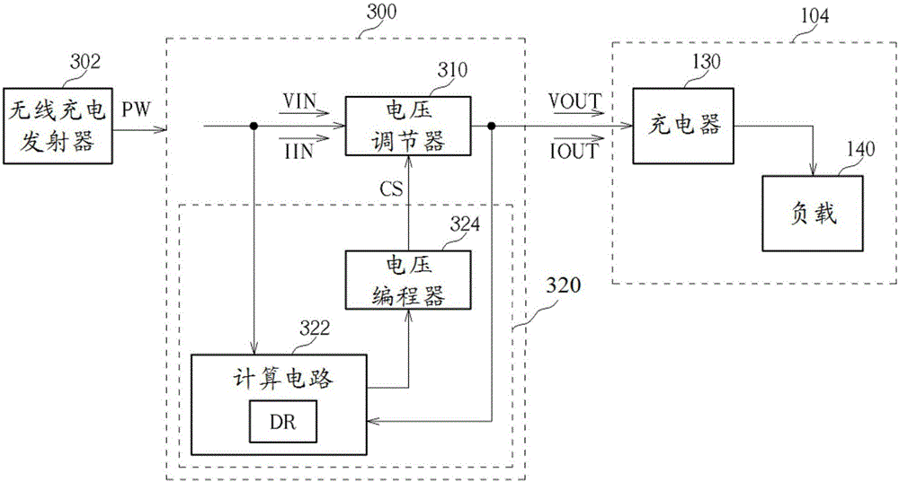
In particular, when a wireless PRU supplies power to a switching charger using AICC, the switching charger tracks the maximum power capacity of the wireless PRU, however, since the wireless PRU has no power limit, the wireless PTU can easily crash

Method used


Image

  • Power Transfer Circuit And Method Utilizing Power Capability Proclamation To Transfer Electrical Power To Charger
  • Power Transfer Circuit And Method Utilizing Power Capability Proclamation To Transfer Electrical Power To Charger
  • Power Transfer Circuit And Method Utilizing Power Capability Proclamation To Transfer Electrical Power To Charger

Examples


Embodiment Construction

[0017] The following description is a preferred embodiment of the present invention, which is only used to illustrate the technical features of the present invention, but not to limit the scope of the present invention. While certain terms are used throughout the specification and claims to refer to specific elements, those skilled in the art should understand that manufacturers may use different names for the same element. Therefore, the specification and claims do not use the difference in name as the way to distinguish components, but use the difference in function of the components as the basis for the difference. The terms "element", "system" and "apparatus" used in the present invention may be a computer-related entity, where the computer may be hardware, software, or a combination of hardware and software. The terms "comprising" and "including" mentioned in the following description and claims are open terms, so they should be interpreted as "including, but not limited ...


PUM


Abstract

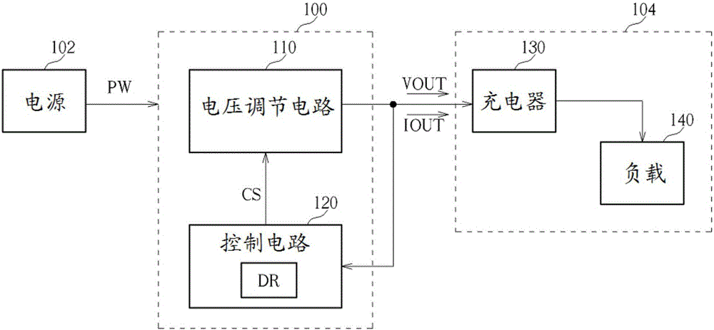
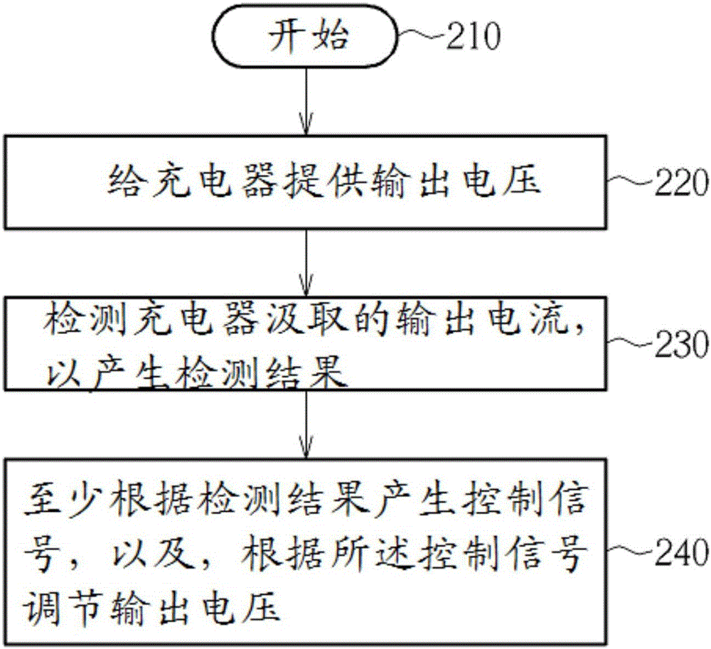
A power transfer circuit for transferring electrical power from a power source to a charger is provided. The power transfer circuit includes a voltage regulation circuit and a control circuit. The voltage regulation circuit is arranged for providing an output voltage for the charger, and adjusting the output voltage according to a control signal, wherein the charger draws an output current from the voltage regulation circuit according to the output voltage. The control circuit is coupled to the voltage regulation circuit, and is arranged for detecting the output current to generate a detection result, and generating the control signal at least according to the detection result.

Description

technical field [0001] The present invention relates to power transfer, and more particularly, to a power transfer circuit and related power transfer method for declaring power capability proclamation in advance to transfer electric power from a power source to a charger. Background technique [0002] Traditional switching chargers utilize adaptive input current control (AICC) to regulate the input current to track the maximum power capability of the adapter, and also utilize poor adapter management (PAM) to set the input current limit regulation to avoid direct current (DC) bus voltage collapse (such as undervoltage lockout (UVLO)), and to allow poor adapters to continue performing battery charging. [0003] However, the power of the wireless power receiver unit (PRU) is limited by the power and coil efficiency of the wireless power transmitter unit (PTU), and the PTU is prone to collapse when providing power to a switching charger using AICC . In particular, when a wirel...

Claims


Application Information

Patent Timeline
IPC IPC(8): H02J50/10H02J7/00
CPCH02J7/025H02J7/007H02J50/80H02J50/10H02J7/00034H02M1/0003
Inventor 丁明强林富祈
Owner MEDIATEK INC
Learn More