Novel low-commutation torque ripple brushless direct-current motor

A technology of brushed DC motors and DC motors, which is applied in the direction of electrical components, electromechanical devices, etc., can solve the problems of large commutation torque pulsation, reduce noise and vibration, improve stability, and reduce electromagnetic commutation torque pulsation. small effect

Active Publication Date: 2017-06-23
BEIJING INSTITUTE OF TECHNOLOGYGY
View PDF3 Cites 3 Cited by
  • Summary
  • Abstract
  • Description
  • Claims
  • Application Information

AI Technical Summary

Problems solved by technology

[0006] The purpose of the present invention is to provide a novel brushless DC motor with low commutatio

Method used


Image

  • Novel low-commutation torque ripple brushless direct-current motor
  • Novel low-commutation torque ripple brushless direct-current motor
  • Novel low-commutation torque ripple brushless direct-current motor

Examples


Embodiment 1

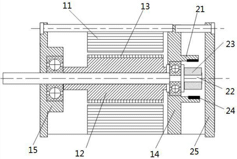
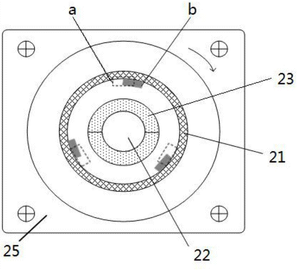
[0036] figure 1 It is a structural sectional view of an embodiment of the novel low commutation torque pulsating brushless DC motor of the present invention. figure 2 It is a schematic diagram of the cross-sectional structure of the sensor device of the present invention.

[0037] see figure 1 and figure 2 As shown, in the embodiment of the present invention, the novel DC brushless motor includes a DC motor and a sensor device.

[0038] The DC motor includes a first stator 11, a first rotor 12, a first rotor magnetic steel 13 and a rear end cover 14; the first stator 11 is coaxially corresponding to the first rotor 12, and the first rotor The magnetic steel 13 is mounted on the outer ring of the first rotor 12 .

[0039] The sensor device includes a second stator 21, a second rotor 22, an annular magnet 23 and a sensor integrated circuit;

[0040] The second stator 21 is ring-shaped, fixed on the rear cover 14 and arranged corresponding to the first rotor 12 , and the s...

Embodiment 2

[0046] The overall structure of the brushless DC motor in Embodiment 2 of the present invention is similar to Embodiment 1, and a position sensor device is also added outside the rear end cover of the DC motor.

[0047] In the second embodiment, the hysteresis installation position b is moved positively by 10° from the optimal commutation position a along the rotation direction of the second rotor.

[0048] The ring magnet 23 is a ring magnet having the same number of pole pairs as the first rotor magnet 13 .

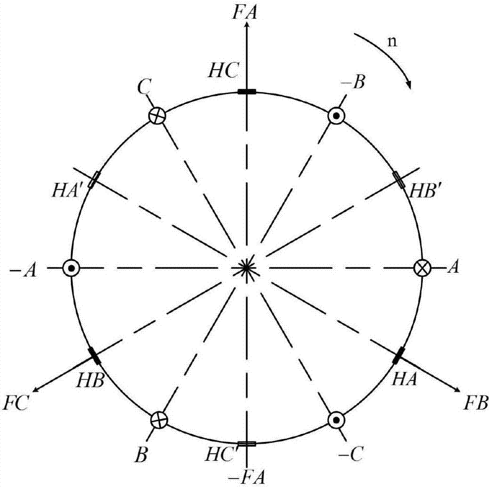
[0049] The position sensor is a Hall sensor, and the marking surface of the Hall sensor points to the rotation axis of the second rotor.

[0050] The embodiment of the present invention adopts the method of placing the position sensor externally, so that the first rotor and the second rotor rotate coaxially and synchronously. Under the three-phase full-wave six-state working mode of the motor, two groups of six Hall sensors can be found on the inner surface of the seco...


PUM


Abstract

The present invention discloses a novel low-commutation torque ripple brushless direct-current motor. The novel low-commutation torque ripple brushless direct-current motor comprises a direct-current motor and a sensor device; the direct-current motor comprises a first stator, a first rotor, first rotor magnetic steel and a rear end cover; the sensor device comprises a second stator, a second rotor, an annular magnet and a sensor integrated circuit; the second stator is annular and is corresponding to the first rotor; the second rotor and the first rotor rotate coaxially and synchronously; the periphery of the second rotor is provided with the annular magnet; the sensor integrated circuit is fixed onto the inner peripheral surface of the second stator; the sensor integrated circuit comprises position sensors for collecting the position signals of the second rotor; the position sensors are mounted in hysteresis mounting positions; and the hysteresis mounting positions are obtained by forwardly moving an optimal commutation position along the forward direction of the rotation of the second rotor by 5 to 10 degrees. According to the novel low-commutation torque ripple brushless direct-current motor of the invention adopted, electromagnetic torque ripples generated during the commutation process of the brushless direct-current motor can be decreased, the torque performance of the motor can be improved, and the installation difficulty of a Hall sensor can be reduced.

Description

technical field [0001] The invention relates to the technical field of DC motors, in particular to a novel low commutation torque pulsating brushless DC motor. Background technique [0002] For brushless DC motors, the sensor is set to obtain the position signal of the rotor during the operation of the brushless DC motor, and the commutation information that the motor should have in the corresponding state can be calculated from the signal, and the power switch is turned on and off according to the principle of commutation, so that A step-by-step rotating magnetic field is formed in the air gap to drive the permanent magnet rotor to rotate continuously. The accuracy of position information has a great impact on the commutation performance. Inaccurate position signals may increase torque ripple, motor vibration, etc., and in severe cases, cause motor commutation failure. However, the commutation torque ripple of the brushless DC motor cannot be eliminated. There are two reas...

Claims


Application Information

Patent Timeline
IPC IPC(8): H02K29/03H02K29/08H02K16/00
CPCH02K16/00H02K29/03H02K29/08
Inventor 陈振王浩宇刘向东赵静
Owner BEIJING INSTITUTE OF TECHNOLOGYGY
Why Eureka
Try Eureka