
Video interaction control method and device

A technology of video interaction and control device, which is applied in closed-circuit television systems, voice analysis, instruments, etc., to achieve the effects of being conducive to large-scale promotion, convenient use and simple structure

Pending Publication Date: 2017-06-23
SHENZHEN LIGHT LIFE TECH CO LTD
View PDF4 Cites 23 Cited by
  • Summary
  • Abstract
  • Description
  • Claims
  • Application Information

AI Technical Summary

Problems solved by technology

[0004] The present invention is to overcome the deficiencies of the prior art and provide a method that can solve the problems of automatically starting video nursing, video calling and video interaction. Specifically, the embodiment of the present invention provides a video interaction control method and device

Method used


Image

  • Video interaction control method and device
  • Video interaction control method and device
  • Video interaction control method and device

Examples


Embodiment 1

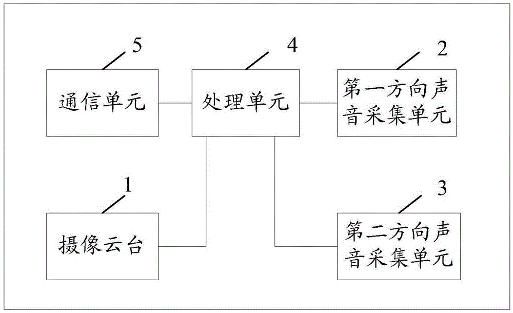
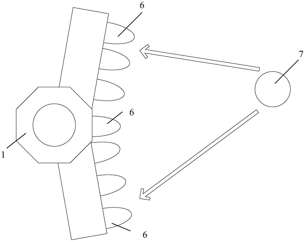
[0036] An embodiment of the present invention provides a video interactive control device, see figure 1 , the device includes: a camera platform 1 , a sound collection unit 2 in the first direction, a sound collection unit 3 in the second direction, a processing unit 4 , and a communication unit 5 .

[0037] The camera platform 1 is used to obtain video information. The camera platform 1 includes a camera and a servo mechanism for controlling the selection of the camera. The camera platform 1 is connected to the processing unit 4, and the signals transmitted during the period include video and audio data and cloud data from the processing unit 4. The platform rotation control signal may also include the platform lifting signal. In this embodiment, the processing unit 4 can be integrated with the imaging platform 1 .

[0038] The first direction sound collection unit 2 is configured to acquire first sound information. Can be implemented with one or more microphones. The seco...

Embodiment 2

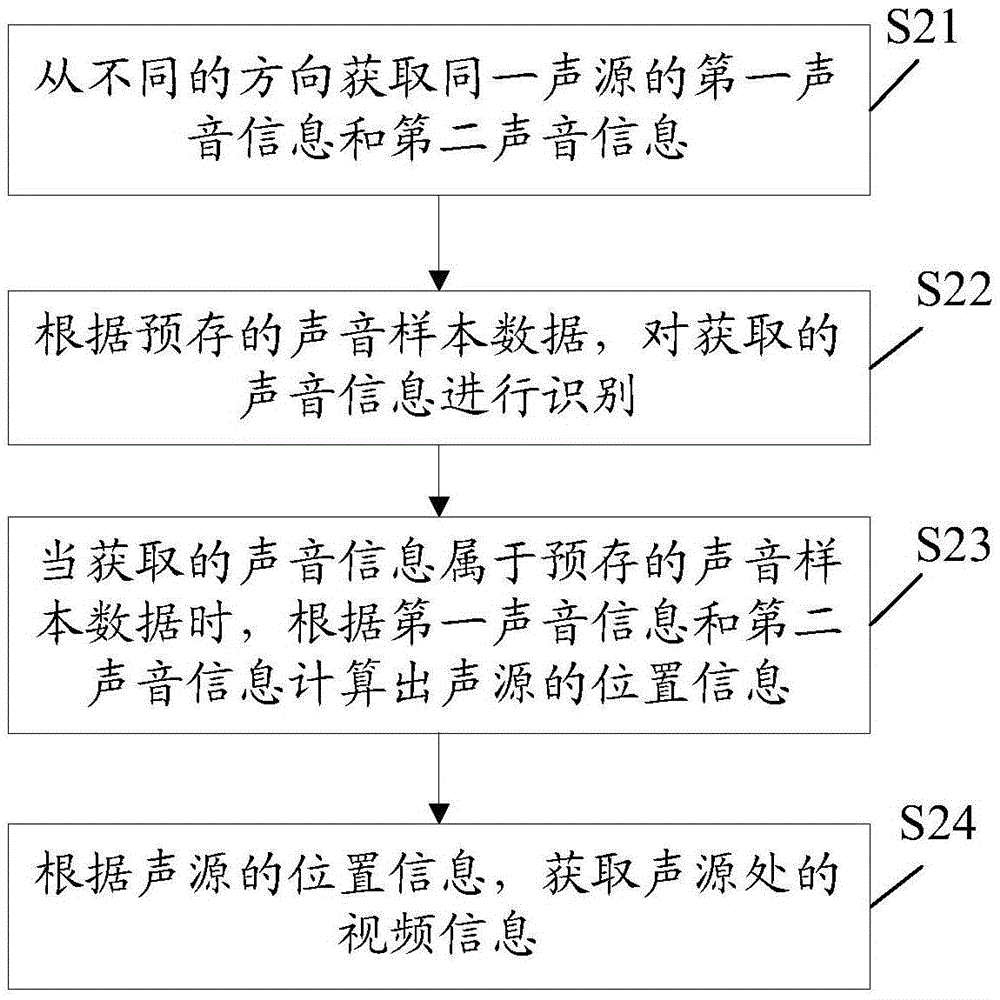
[0060] An embodiment of the present invention provides a video interaction control method, which is applicable to the video interaction control device described in Embodiment 1, see image 3 , the method includes:

[0061] Step S21, acquiring the first sound information and the second sound information of the same sound source from different directions.

[0062] In this embodiment, the first direction sound collection unit and the second direction sound collection unit may be used to obtain sound information of the same sound source from different directions.

[0063] In step S22, the acquired voice information is identified according to the pre-stored voice sample data.

[0064] In this embodiment, the processing unit of the video interaction control device may be used to perform the recognition work, that is, to judge whether the acquired sound information belongs to the pre-stored sound sample data.

[0065] Step S23, when the acquired sound information belongs to the pre...


PUM


Abstract

The invention discloses a video interaction control method and device, and belongs to the technical field of monitoring. The device comprises a PTZ camera (1), a first direction sound collection unit (2), a second direction sound collection unit (3), a processing unit (4), and a communication unit (5). The processing unit (4) is used for recognizing the obtained sound information, calculating the position information of a sound source according to first sound information and second sound information when the obtained sound information belongs to preset sound sample data, and controlling the PTZ camera (1) to turn to the sound source according to the calculated position information. Through the recognition of the sound generated by the sound source, the device controls the PTZ camera (1) to turn to the sound source when the sound generated by the sound source belongs to the preset sound sample data, and carries out the interaction of the obtained video information of the sound source and a preset video interaction object, thereby enabling the emergency of the sound source to be timely fed back to the video interaction object, and enabling the sound source to be rescued or cared timely.

Description

technical field [0001] The invention relates to the technical field of monitoring, in particular to a video interactive control method and device. Background technique [0002] With the development of modern society, population aging is the trend of population development in the world today, and population aging has increasingly become a major population issue of concern to all countries in the world. The increase of the elderly means on the one hand that these elderly people need to be taken care of in their lives, so as to avoid timely assistance when accidents occur due to their physical conditions. In modern society, the elderly mainly rely on their children or nursing staff to take care of them. However, due to the fast pace of life, children are generally busy with work, and it is difficult to have a lot of time to accompany them. The number of nursing staff is limited, and it is difficult to take care of the growing number of elderly people. , In the daily life of th...

Claims


Application Information

Patent Timeline
IPC IPC(8): H04N7/18H04N7/14G10L15/28
CPCH04N7/14H04N7/18G10L15/28
Inventor 陈芒
Owner SHENZHEN LIGHT LIFE TECH CO LTD
Learn More