Underground personnel locating and rescuing system and under ground personnel locating method

A personnel positioning and wireless technology, applied in the field of rescue systems, can solve the problems of not being able to find trapped miners, waste of effort, and bulky communication equipment, so as to improve mining efficiency and benefits, reduce self-loss, and improve rescue effects.

Inactive Publication Date: 2006-11-08
宁波市艾因斯科技有限公司
View PDF0 Cites 15 Cited by
  • Summary
  • Abstract
  • Description
  • Claims
  • Application Information

AI Technical Summary

Problems solved by technology

[0005] On the other hand, the PED system designed in Australia has a strong ability to penetrate rock and soil layers (up to 200 m thick), and can realize direct surface-to-downhole communication, but its surface and downhole loop antennas are very large in size (minimum 10m in diameter, up to 120m), and cannot realize direct communication from underground to surface
[0006] The above-mentioned various devices have the following common defects: 1) the size of the antenna is too large, and the communication equipment is heavy; 2) only one-way communication from the ground to the underground can be realized; 3) special communication cables or a large number of existing 4) It is required to know the underground geographic information; 5) It is impossible to accurately determine the specific location of the miners; 6) The safety of the rescuers themselves is not considered, and the ground personnel, rescuers and underground miners are not connected through the wireless network. effectively linked
[0009] These RFID-based systems have at least the following problems in practical applications: 1) It is completely feasible for the monitoring data to be transmitted by cable when the mine is operating normally, but it is likely that the cable will be broken or burned due to landslides and other reasons during mine disasters, so that it cannot work normally. transfer data
2) It is feasible for the monitoring node to be powered by the underground power supply when the mine is operating normally, but the underground power supply is likely to be cut off in the event of a mine disaster, which will cause the monitoring node to fail to work normally
3) The coverage of monitoring nodes is generally tens of meters or even hundreds of meters, so replacing the position of miners with the position of monitoring nodes will cause a large error (generally more than 20 meters)
The former is time-consuming and labor-intensive, while the latter will cause large errors
5) It is obviously cumbersome to arrange wired cables and connect corresponding monitoring nodes every time the mine advances a small distance (such as 50 meters). Cables and monitoring nodes will also cause miners to be invisible when they are in certain locations
[0010] In addition, the passive RFID identification card designed in the miner's cap has at least the following defects in practical applications: 1) when a mining accident occurs, the miner's cap is likely to be detached due to various reasons (such as smashed stones, miners running to escape, etc.) As a result, even if the rescuers find the RFID identification card, they cannot find the trapped miners, which is a waste of effort
2) Passive RFID identification cards cannot actively emit strong wireless signals
In this way, if the mine disaster is accompanied by landslides and other phenomena, even if the rescuers send out a strong search and rescue signal and the RFID identification card receives the signal, they cannot penetrate the rock or soil layer and give a strong response signal, so that the rescuers cannot determine whether they are trapped. The exact location of the miners

Method used


Image

  • Underground personnel locating and rescuing system and under ground personnel locating method
  • Underground personnel locating and rescuing system and under ground personnel locating method
  • Underground personnel locating and rescuing system and under ground personnel locating method

Examples


Embodiment Construction

[0031] The present invention will be further described in detail below in conjunction with the accompanying drawings and embodiments.

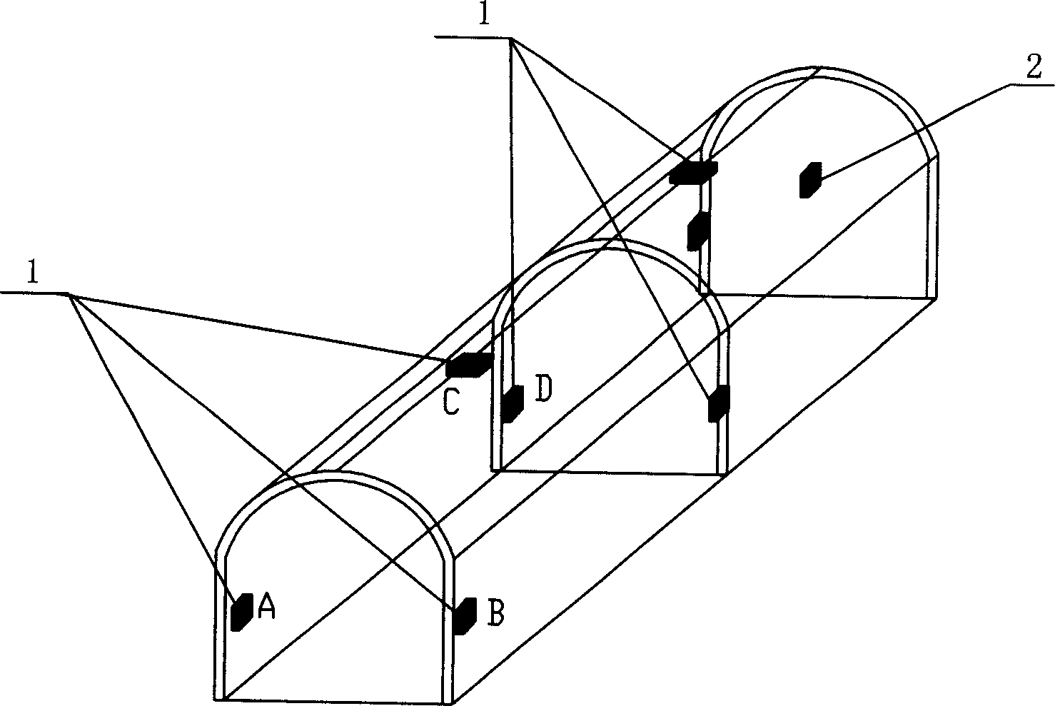
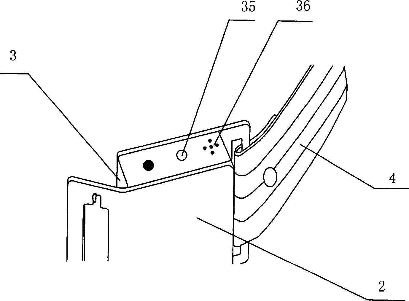
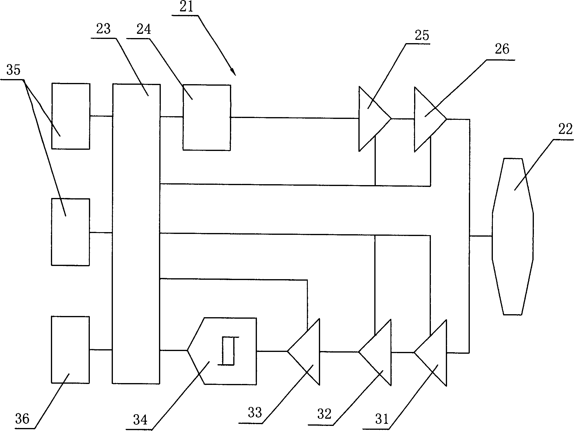
[0032] As shown in the figure, an underground personnel positioning and rescue system includes a wireless monitoring node network composed of a plurality of wireless monitoring node groups 1 arranged along the mine road and a wireless tracker 2 worn by the miners. The distance between the node groups is 25 meters. The wireless monitoring node group 1 is composed of three wireless monitoring nodes. The three wireless monitoring nodes A, B, and C of the first group of wireless monitoring node groups are respectively set in the mine tunnel at the entrance of the mine tunnel. The two sides and the top of the belt, the wireless tracker 2 is a belt-type wireless tracker, including a tracker circuit 21 and a first antenna 22, the tracker circuit 21 is arranged on the belt head 3, and the first antenna 22 is arranged in the belt 4 The single-loop loop...


PUM


Abstract

The underground personnel locating and rescuing system and method features the radio monitoring node network comprising radio monitoring node sets arranged along the mine drafts and the miners' carried radio trackers. Each of the radio monitoring node sets consists of three radio monitoring nodes on sides and top of mine drift. The present invention constitutes automatic 3D locating system with underground radio network to monitor the locations of the miners, especially in mine disaster.

Description

technical field [0001] The invention relates to a rescue system, in particular to an underground personnel positioning rescue system and an underground personnel positioning method. Background technique [0002] The existing underground personnel positioning system is mainly a communication system between ground personnel and underground personnel. In the 1820s, the potential for wireless communication with miners trapped underground was realized through experiments with underground reception of long waves. However, it was impossible to design a practical wireless communication system with the technical level at that time. Since then, further research using electromagnetic waves downhole has mainly turned to geophysical detection. In the 1840s, T.L. Wadley conducted the first basic research on electromagnetic waves penetrating rock formations (Trough The Earth, abbreviated as TTE), which set off an upsurge in the study of underground electromagnetic wave propagation in Sou...

Claims


Application Information

Patent Timeline
Patent Type & Authority Applications(China)
IPC IPC(8): E21F17/18E21F11/00
Inventor 钟志光
Owner 宁波市艾因斯科技有限公司
Why Eureka
Try Eureka