
A super-compliant segmented stent and its weaving method

A compliance and transition technology, applied in the field of medical equipment, can solve the problems of easy displacement, poor compliance, and poor stent compliance, and achieve the effect of fixing the stent and reducing the displacement of the stent.

Active Publication Date: 2019-04-05
MICRO TECH (NANJING) CO LTD
View PDF6 Cites 0 Cited by
  • Summary
  • Abstract
  • Description
  • Claims
  • Application Information

AI Technical Summary

Problems solved by technology

Or after the polymer film is attached to the surface of the stent, the stent is heated as a whole. Because the film is attached to the surface of the stent as a whole, the compliance of the stent is not good and it is easy to shift
A nickel-titanium wire is used for the weaving of the traditional metal bare frame, and the whole frame is woven into a grid shape without moving parts, so the compliance is not good

Method used


Image

  • A super-compliant segmented stent and its weaving method
  • A super-compliant segmented stent and its weaving method
  • A super-compliant segmented stent and its weaving method

Examples


Embodiment 1

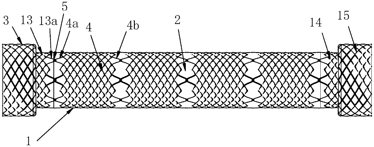
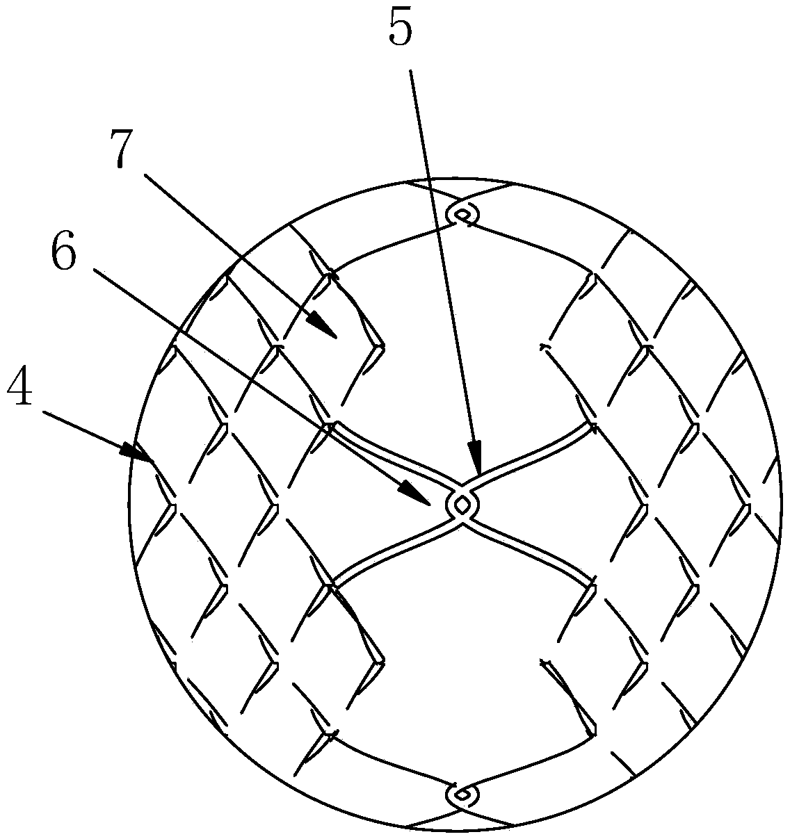
[0032] Such as figure 1 with figure 2 , The connecting structure 2 at one end of the segmented part 4 includes a high pointed head 6 and a low round head 7. The high pointed head and the low round head are alternately arranged at intervals, starting with a high pointed head, in a clockwise direction, and all odd-numbered ends are The high pointed head and the even-numbered head ends are all low round heads, and the high pointed heads are connected to the high pointed heads of the adjacent segments to form the lock structure 5. The single high point is the lock ring 6, and the lock ring and the lock ring are paired to form a lock structure.

[0033] This embodiment also includes a weaving method: including the following steps:

[0034] Step 1: Use wire to knit the cup structure 3 from either end of the bracket until the cup structure is knitted;

[0035] Step 2: Use wire to weave a cup transition section 13, and weave a set of lock rings 13a at the end of the cup transition section;...

Embodiment 2

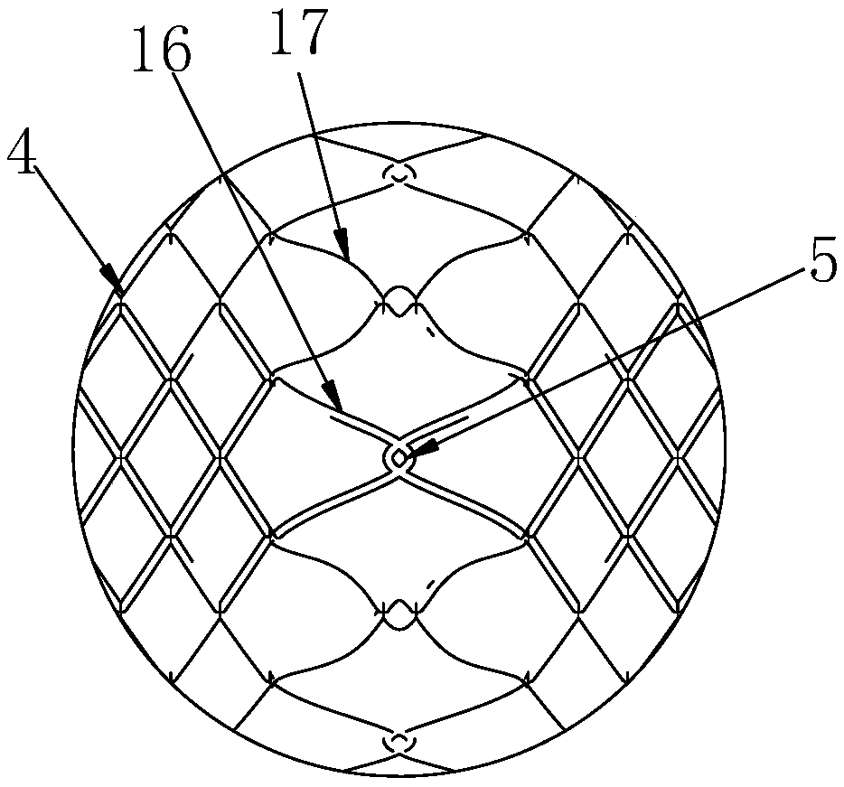
[0042] Such as image 3 , The connecting structure includes an axial high head 16 and a radial high head 17, the axial high head 16 and the radial high head 17 are alternately arranged at intervals, and the axial high heads of two adjacent sections are connected to the axial high head to form a lock Structure, the radial high head is connected to the radial high head to form a lock structure.

Embodiment 3

[0044] Such as Figure 4 , The odd-numbered heads of each segmented stent are woven into high-pointed head 8, and the even-numbered heads are woven into low-pointed head 9. The interconnection between the segmented stents is through the high-pointed head of one segment and the low The pointed ends are connected to each other to form a lock structure 5.


PUM


Abstract

The invention provides a super-compliance subsection support which comprises a support body and cup rim portions at the two ends of the support body. The support body is composed of two or more subsection portions. A connecting structure comprises high tip ends and low circular ends at the two ends of the subsection portions, the high tip ends and the low circular ends of the subsection portions are arranged alternately, and the high tip ends of every two adjacent subsection portions form a lock catch structure. The connecting structure comprises high axial ends and high radial ends arranged at the two ends of the subsection portions, the high radial ends and the high radial ends of the ends of the subsection portions are arranged alternately, the high axial ends at every two adjacent subsection portions form a first lock catch structure, and the high axial ends at every two adjacent subsection portions form a second lock catch structure.

Description

Technical field [0001] The invention relates to the field of medical equipment, in particular to a super-compliant segmented stent and a braiding method thereof. Background technique [0002] The lumen of the human body is narrowed or obstructed due to various reasons and pathological changes. At present, the commonly used method is to implant a metal stent in the stenosis and obstruction to ensure the patency of the lumen. [0003] The current stents include bare metal stents and covered stents. The covering processing method of the covered stents is usually by immersing the entire stent in a polymer liquid and casting the membrane on the wall. Or after the polymer membrane is attached to the surface of the stent, the entire stent is heated. Because the entire membrane is attached to the surface of the stent, the stent has poor compliance and is easy to shift. The braiding of the traditional bare metal frame uses a nickel-titanium wire, and the stent is woven into a grid as a who...

Claims


Application Information

Patent Timeline
Patent Type & Authority Patents(China)
IPC IPC(8): A61F2/90
CPCA61F2/90A61F2002/828
Inventor 韦建宇李玉茜周友琴李传明钱芳沈正华张子蔚李常青冷德嵘
Owner MICRO TECH (NANJING) CO LTD
Learn More