
Hydraulic pipe bending equipment

A hydraulic tube and equipment technology, applied in the field of bending equipment, can solve problems such as the difficulty in ensuring the coaxiality of the hydraulic tube and the bending plate, the difficult control of the bending angle of the hydraulic tube, and the difficulty in ensuring the balance of the equipment, etc., to achieve Avoid edge warping, ensure coaxiality, and facilitate movement

Inactive Publication Date: 2019-01-11
FOSHAN QIANGWEI NEW ENERGY TECH CO LTD
View PDF8 Cites 1 Cited by
  • Summary
  • Abstract
  • Description
  • Claims
  • Application Information

AI Technical Summary

Problems solved by technology

[0003] However, in the practical application of hydraulic pipes, people must first use bending equipment to bend hydraulic pipes. Bending equipment is a common equipment used to bend workpieces. Hydraulic pipes are bent using bending equipment. Now Some hydraulic tube bending equipment has certain problems in use. For example, the bending angle of the hydraulic tube is not easy to control, and the operator needs to have certain work experience. There is also a direct hand to fix the hydraulic tube. It is difficult to ensure the hydraulic pressure. The coaxiality of the tube and the bending plate, the hydraulic tube after bending may sometimes appear warping, which affects the product quality. Although the traditional bending equipment can be moved by using the moving wheel, when it is not moving, the force on the equipment The point is still on the moving wheel. Since the moving wheel itself is movable, after long-term use, the wear and tear of each moving wheel is different. Therefore, it is difficult to ensure the balance of the equipment during the work process. bring certain adverse effects

Method used


Image

  • Hydraulic pipe bending equipment
  • Hydraulic pipe bending equipment
  • Hydraulic pipe bending equipment

Examples


Embodiment Construction

[0031] The following will clearly and completely describe the technical solutions in the embodiments of the present invention with reference to the accompanying drawings in the embodiments of the present invention. Obviously, the described embodiments are only some, not all, embodiments of the present invention. Based on the embodiments of the present invention, all other embodiments obtained by persons of ordinary skill in the art without making creative efforts belong to the protection scope of the present invention.

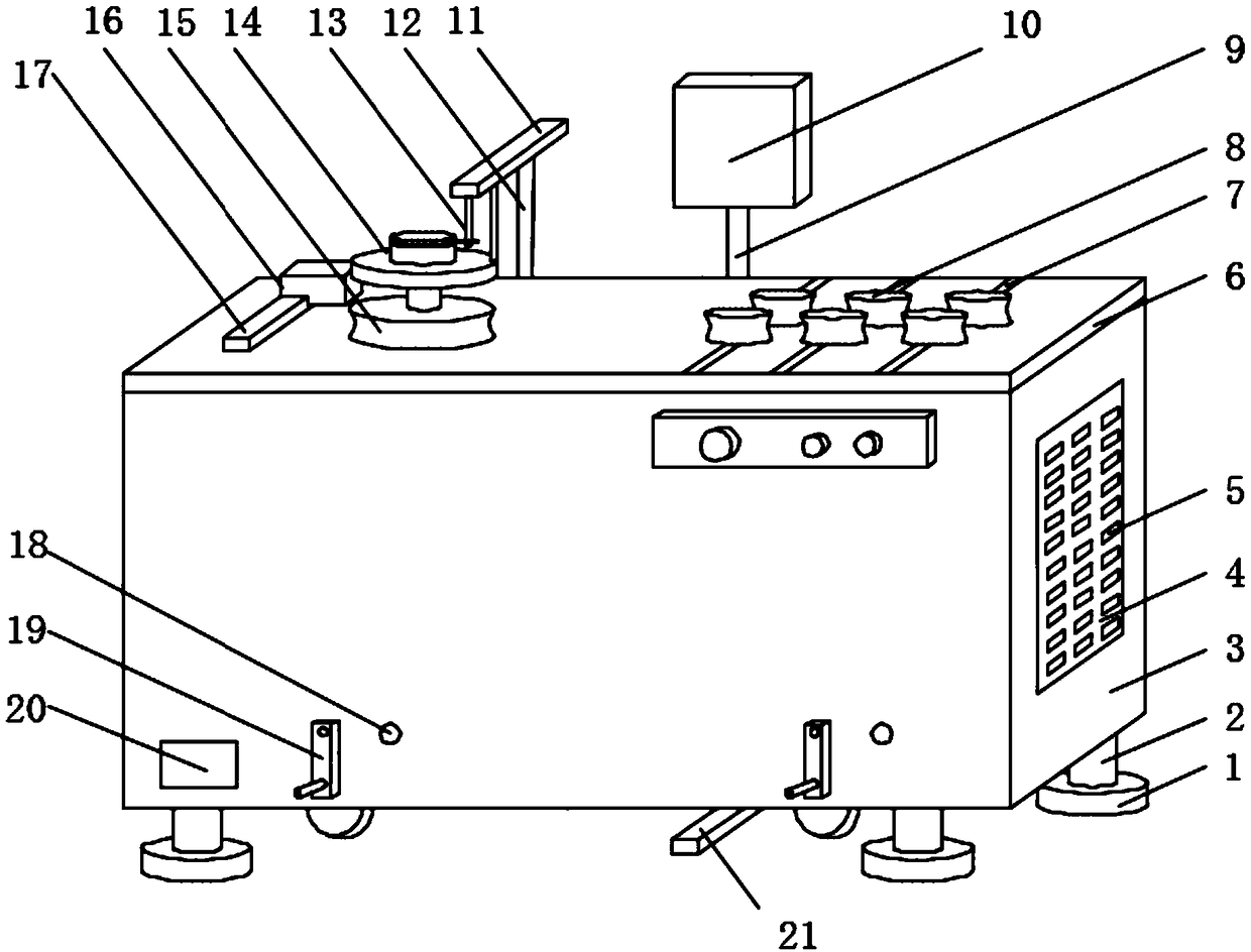
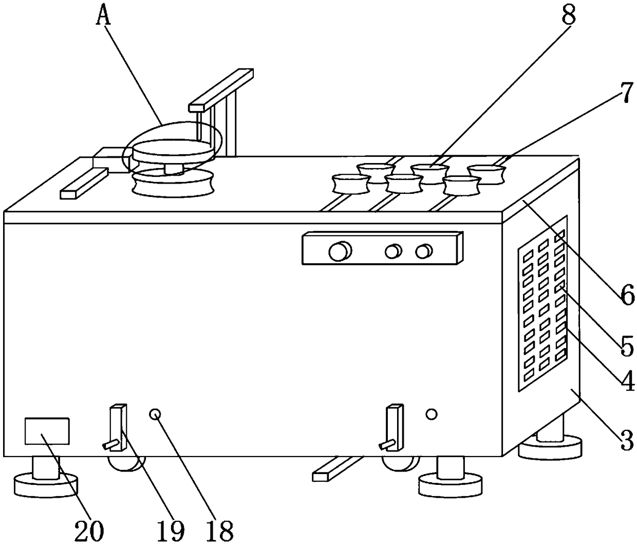
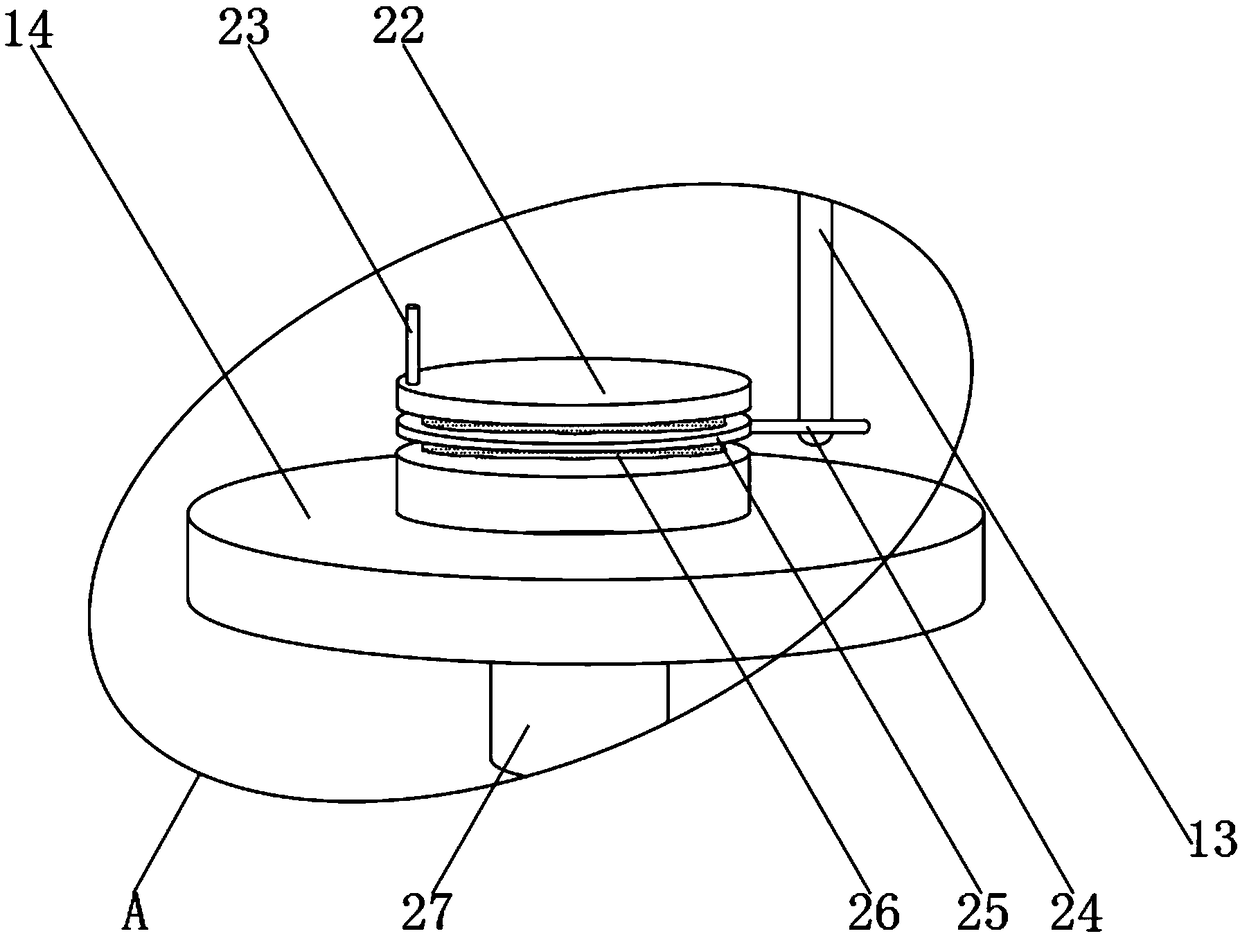
[0032] see Figure 1-6, the present invention provides a technical solution: a hydraulic pipe bending equipment, including a bending machine main body 3, a column 2 is fixedly installed on the outer surface of the lower end of the bending machine main body 3, the column 2 can support the bending machine main body 3, and The outer surface of the lower end of the column 2 is fixedly installed with a base 1, and the outer surface of one side of the main body 3 of...


PUM


Abstract

The invention discloses hydraulic pipe bending equipment. The hydraulic pipe bending equipment comprises a bending machine main body. Stand columns are fixedly installed on the outer surface of the lower end of the bending machine main body, bases are fixedly installed on the outer surfaces of the lower ends of the stand columns, a heat dissipation plate is fixedly installed on the outer surface of one side of the bending machine main body, heat dissipation holes are formed in the outer surface of the heat dissipation plate, and a notice board is fixedly installed on the outer surface of the front end of the bending machine main body. A working platform is fixedly installed on the outer surface of the upper end of the bending machine main body, a compression roller and a bending disc are movably installed on the outer surface of the upper end of the working platform, a sliding rod is arranged on one side of the bending disc, and the sliding rod is fixedly installed on the outer surfaceof the upper end of the working platform. The hydraulic pipe bending equipment can conveniently control the bending angle, clamp a bending pipe conveniently and be moved conveniently, and when the hydraulic pipe bending equipment is not moved, the stress point of the equipment can be transferred from moving wheels to the bases to ensure the balance of the equipment.

Description

technical field [0001] The invention relates to the field of bending equipment, in particular to a hydraulic pipe bending equipment. Background technique [0002] The hydraulic tube is an important component of hydraulic equipment. The quality of the hydraulic tube is one of the keys to the normal performance of the hydraulic system. In practical applications, the hydraulic tube is divided into multiple types, which are related to mechanical transmission, electric Compared with the transmission, the hydraulic tube has the advantages of being easy to carry and can realize overload protection, etc., and has been widely used by people. [0003] However, in the practical application of hydraulic pipes, people must first use bending equipment to bend hydraulic pipes. Bending equipment is a common equipment used to bend workpieces. Hydraulic pipes are bent using bending equipment. Now Some hydraulic tube bending equipment has certain problems in use. For example, the bending angl...

Claims


Application Information

Patent Timeline
IPC IPC(8): B21D7/14B21D7/16B21D43/00
CPCB21D7/14B21D7/16B21D43/003
Inventor 周莹
Owner FOSHAN QIANGWEI NEW ENERGY TECH CO LTD
Learn More