Visual-positioning glue dispenser

A technology of visual positioning and dispensing machine, which is applied in the direction of coating and liquid coating device on the surface, etc. It can solve the problems of complicated product feeding, low dispensing efficiency and large dispensing error rate, and achieve dispensing error Low rate, high dispensing efficiency, precise positioning effect

Inactive Publication Date: 2017-06-27
济通云智能科技(东莞)有限公司
View PDF8 Cites 4 Cited by
  • Summary
  • Abstract
  • Description
  • Claims
  • Application Information

AI Technical Summary

Problems solved by technology

[0003] But for the existing glue dispensing machine, there is a problem: for the existing glue dispensing machine, its glue dispensing position is fixed, and in the glue dispensing process, the product needs to be moved by matching the corresponding moving components with the fixture To the dispensing position, at the same time, when assembling the product before dispensing, it is necessary to place the products one by one according to the limited orientation. Therefore, the existing dispensing machine has complicated operations when feeding products and dispensing products. , inaccurate positioning, large dispensing error rate, and low dispensing efficiency; moreover, when the existing dispensing machine is used, the product loading is complicated, time-consuming and cumbersome

Method used


Image

  • Visual-positioning glue dispenser
  • Visual-positioning glue dispenser
  • Visual-positioning glue dispenser

Examples


Embodiment Construction

[0022] The present invention will be described in further detail below in conjunction with the accompanying drawings.

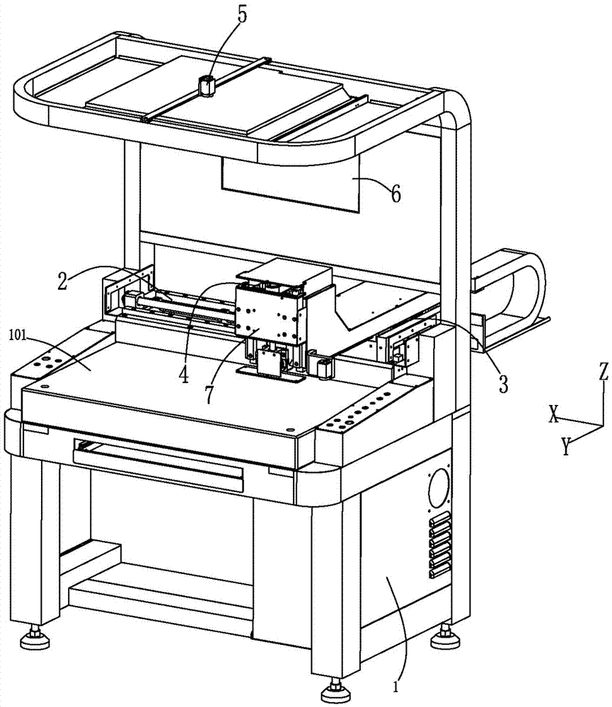
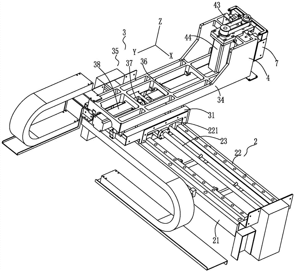
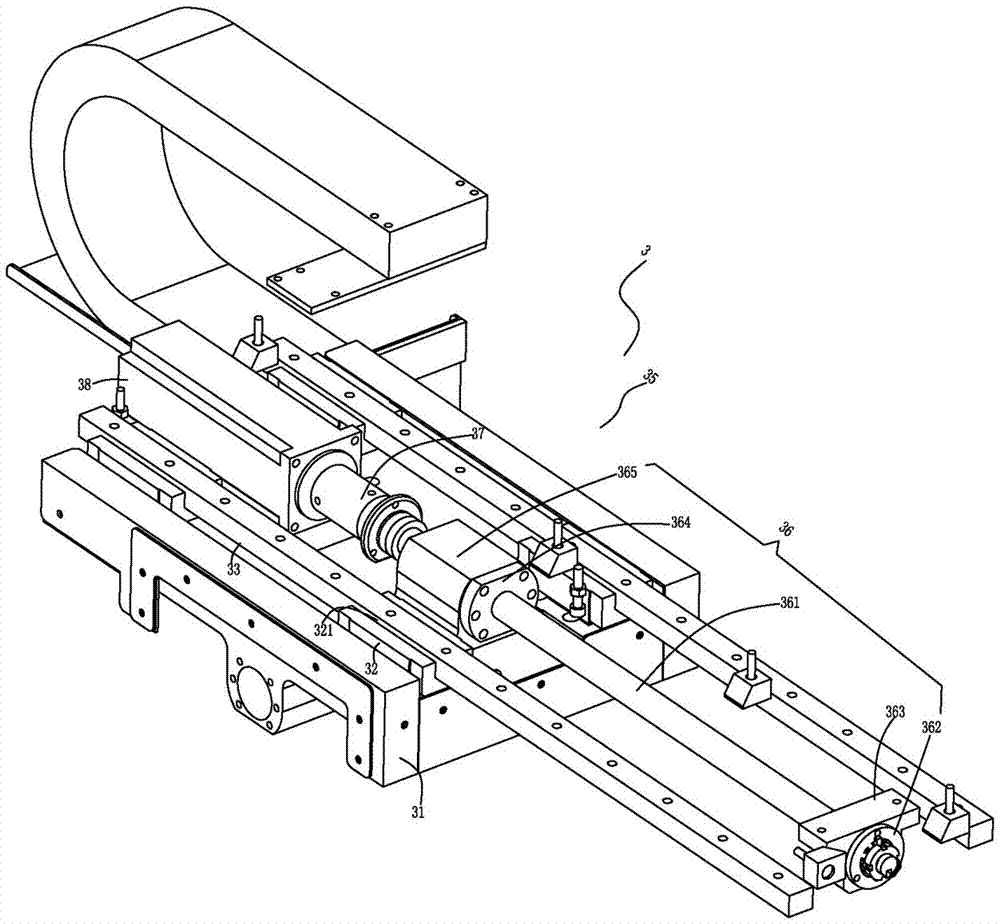
[0023] attached Figure 1-5 An example of a specific embodiment of the present invention is given. The present invention is a visual positioning glue dispensing machine, which includes a machine platform 1, and an X-direction assembly 2 is arranged on the glue dispensing platform 101 of the machine platform 1. The X-direction A Y-direction component 3 is installed on the component 2, and the X-direction component 2 can drive the Y-direction component 3 to move in the X direction. During work, the Y-direction component 3 is movable on the X-direction component 2 Move (along the X direction); the Y-direction assembly 3 is provided with a Z-direction assembly 4, and the Z-direction assembly 4 is provided with a dispensing gun (the dispensing gun is not shown in the drawings, only the installation position of the dispensing gun is shown ), the Y-direction compon...


PUM


Abstract

The invention discloses a visual-positioning glue dispenser which comprises a dispenser table. An X-direction assembly is arranged on a glue dispensing table of the dispenser table. A Y-direction assembly is arranged on the X-direction assembly, and the X-direction assembly can drive the Y-direction assembly to move in the X direction. A Z-direction assembly is arranged on the Y-direction assembly and provided with a glue dispensing gun, the Y-direction assembly can drive the Z-direction assembly and the glue dispensing gun to move in the Y direction, and the Z-direction assembly can drive the glue dispensing gun to move in the Z direction and conduct glue dispensing on a plastic part on the glue dispensing table. The visual-positioning glue dispenser further comprises a camera device and a control device. The camera device is arranged above the machine table and can take a picture of the plastic part positioned on the glue dispensing table to form an image, and the control device controls the X-direction assembly, the Y-direction assembly and the Z-direction assembly to move in a matched mode according to the position, obtained by imaging of the camera device, of the plastic part, so that the glue dispensing gun is moved to the position matched with the position of the plastic part to complete glue dispensing. The visual-positioning glue dispenser is precise in positioning, easy to operate, low in glue dispensing error rate and high in glue dispensing efficiency.

Description

technical field [0001] The invention relates to the field of auto parts processing equipment, in particular to a visual positioning glue dispenser. Background technique [0002] With the improvement of living standards, automobiles have become a common means of transportation in people's daily life. In the processing of auto parts, especially the processing of plastic parts, it is often necessary to use a dispenser to dispense glue. After gluing, combine the scattered plastic parts into matching products; or dispense glue in the gaps of the plastic parts to fill the gaps. [0003] But for the existing glue dispensing machine, there is a problem: for the existing glue dispensing machine, its glue dispensing position is fixed, and during the glue dispensing process, the product needs to be moved by matching the corresponding moving components with the fixture To the dispensing position, at the same time, when assembling the product before dispensing, it is necessary to place ...

Claims


Application Information

Patent Timeline
Patent Type & Authority Applications(China)
IPC IPC(8): B05C5/02B05C13/02B05C11/00
CPCB05C5/02B05C11/00B05C13/02
Inventor 田仁超谭献勇
Owner 济通云智能科技(东莞)有限公司
Why Eureka
Try Eureka