Accurately processed automatic assembly machine for multi-stage components of motor rotor shaft

A technology for motor rotors and assembly machines, which is applied to assembly machines, metal processing, metal processing equipment, etc., and can solve problems such as installation offset, waste of processing time, and placement offset.

A technology for motor rotors and assembly machines, which is applied to assembly machines, metal processing, metal processing equipment, etc., and can solve problems such as installation offset, waste of processing time, and placement offset.

CN106891149BActive Publication Date: 2018-10-12周胡琴

Image

  • Accurately processed automatic assembly machine for multi-stage components of motor rotor shaft
  • Accurately processed automatic assembly machine for multi-stage components of motor rotor shaft
  • Accurately processed automatic assembly machine for multi-stage components of motor rotor shaft

Examples


Embodiment Construction

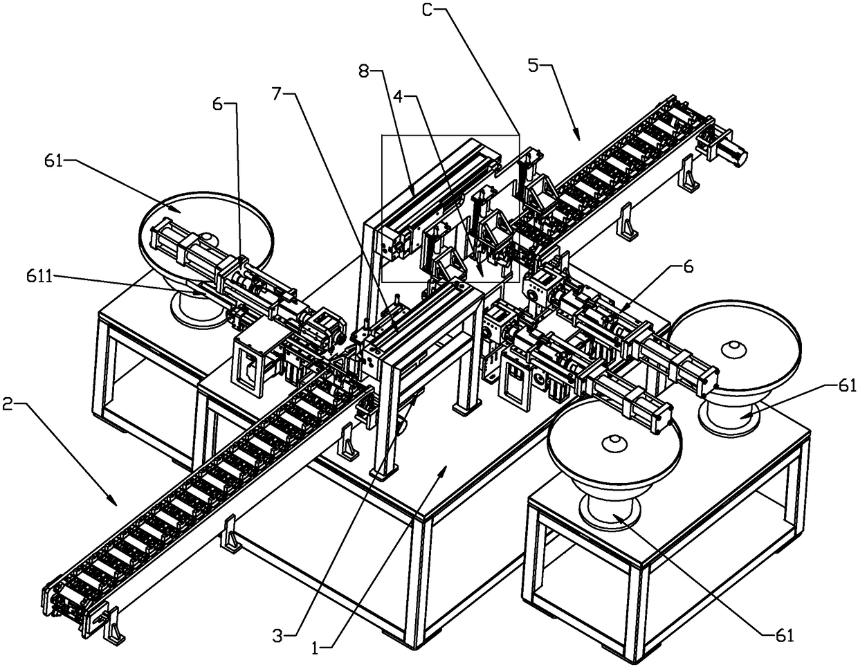
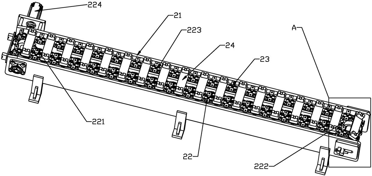
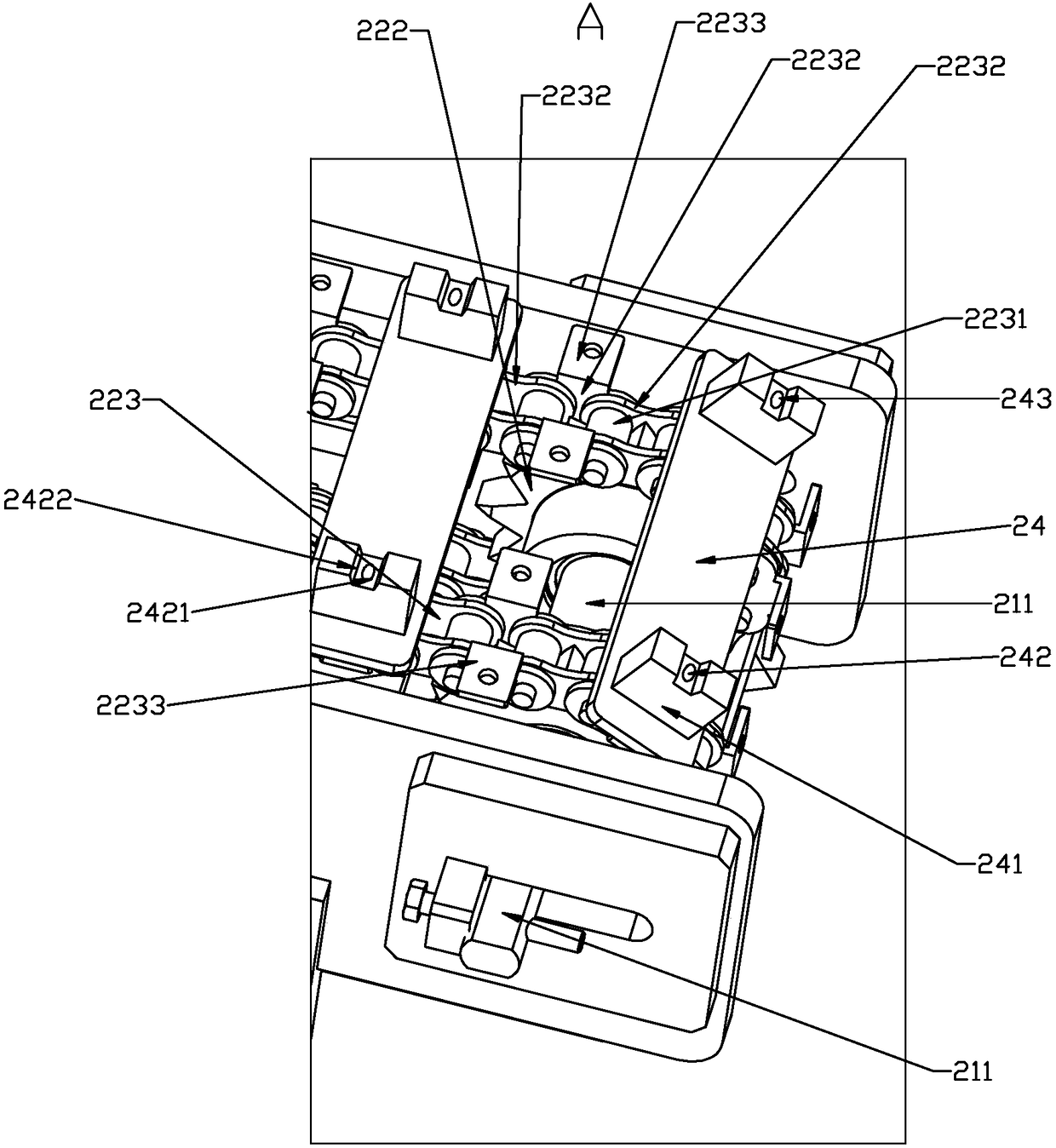
[0033] Such as figure 1 — Figure 10 As shown, the present invention discloses an automatic assembly machine for multi-stage components of motor rotor shaft with accurate processing, which includes a working table 1, on which a feeding device 2, a first processing seat 3, and a second processing seat 4 are sequentially arranged And the discharge device 5, the working surface 1 is located on the side of the first processing seat 3 and the second processing seat 4, and an assembly device 6 is provided. Between the feeding device 2 and the first processing seat 3, a motor rotor shaft is arranged to switch positions in sequence. The front transport device 7, the rear transport device 8 that switches the position of the motor rotor shaft sequentially between the first processing seat 3, the second processing seat 4 and the discharge device 5, the feed device 2 and the discharge device 5 respectively include Track support 21, left gear belt assembly 22, right gear belt assembly 23 ...


PUM


Abstract

The invention relates to an automatic motor rotor shaft multi-level component assembling machine capable of achieving accurate machining. The automatic motor rotor shaft multi-level component assembling machine comprises a worktable top. The worktable top is sequentially provided with a feeding device, a first machining base, a second machining base and a discharging device. The part, located on the side faces of the first machining base and the second machining base, of the worktable top is provided with assembling devices. A front conveying device for sequentially switching the positions of motor rotor shafts is arranged between the feeding device and the first machining base. A rear conveying device for sequentially switching the positions of the motor rotor shafts is arranged among the first machining base, the second machining base and the discharging device. Containing grooves are provided with micro moving induction switches, and when the micro moving induction switches corresponding to the assembling devices are extruded, assembling air cylinders are electrified, and the micro moving induction switches are arranged in the containing grooves. By the adoption of the above scheme, the automatic motor rotor shaft multi-level component assembling machine capable of protecting the assembling devices and achieving accurate machining is provided.

Description

technical field [0001] The invention relates to a processing equipment for a motor rotor shaft, in particular to an automatic assembly machine for accurately processing multi-stage components of a motor rotor shaft. Background technique [0002] The motor rotor shaft is a transliteration of the English motor, that is, the motor and the engine. The working principle is to drive the starter rotor to rotate through electromagnetic induction, and the pinion on the rotor drives the engine flywheel to rotate. In order to make the motor rotor shaft have better functionality, after the motor rotor shaft is processed, it is necessary to install some assembly parts on the motor rotor shaft, such as sealing rings, gears, etc. The traditional installation method is to manually place it on the punching machine After installing one component, collect and move it to the next station to install another component. On the one hand, it wastes processing time and reduces processing efficiency....

Claims


Application Information

Patent Timeline
12 Oct 2018
Publication
CN106891149B
IPC
B23P21/00; B23P19/00
CPC
B23P19/007; B23P21/00
Inventors
周胡琴