
Upper limb exoskeleton storing energy by virtue of linear spring with adjustable load

A linear spring and exoskeleton technology, which is applied in the field of adjustable load linear spring energy storage upper limb exoskeleton, can solve the problem that the gravity balance exoskeleton cannot be adjusted, and achieve the effects of increasing practicability, reducing output force and reducing cost

Active Publication Date: 2017-06-27
HARBIN INST OF TECH
View PDF3 Cites 4 Cited by
  • Summary
  • Abstract
  • Description
  • Claims
  • Application Information

AI Technical Summary

Problems solved by technology

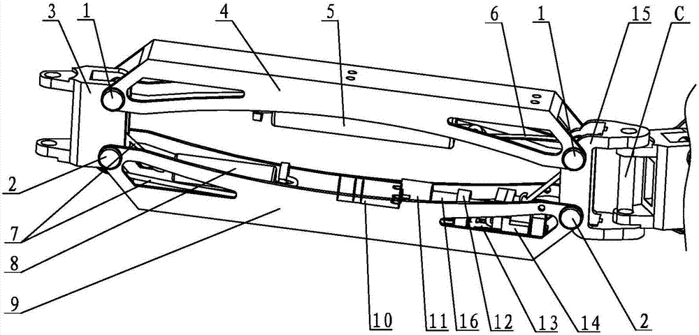
[0004] In order to solve the problem that the existing gravity balance exoskeleton cannot be automatically adjusted for different loads, the present invention proposes an adjustable load linear spring energy storage upper limb exoskeleton

Method used


Image

  • Upper limb exoskeleton storing energy by virtue of linear spring with adjustable load
  • Upper limb exoskeleton storing energy by virtue of linear spring with adjustable load
  • Upper limb exoskeleton storing energy by virtue of linear spring with adjustable load

Examples


specific Embodiment approach 1

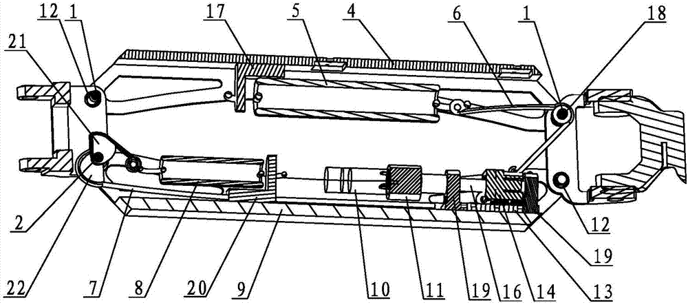
[0013] Specific implementation mode one: combine Figure 1 ~ Figure 3 Describe this embodiment, this embodiment includes big arm A, forearm B, hand C, elbow rotating shaft D and hand rotating shaft E, the structure of big arm A and small arm B is the same, and big arm A includes front joint 3, Boom upper connecting rod 4, gravity balance spring 5, first steel wire rope 6, second steel wire rope 7, reverse force spring 8, big arm lower connecting rod 9, motor 10, reducer 11, slide rail 13, lead screw nut 14 , rear joint 15, lead screw 16, gravity balance spring holder 17, reverse force spring holder 20, first cam 21, second cam 22, two upper rotating shafts 1, two lower rotating shafts 2, two leading screws Bearing block 19 and four bearings 12, two upper rotating shafts 1 and two lower rotating shafts 2 are arranged in a rectangle, the front joint 3 is hinged with the upper rotating shaft 1 and the lower rotating shaft 2 on the left side through bearings 12, and the rear joint...

specific Embodiment approach 2

[0015] Specific implementation mode two: combination image 3 This embodiment will be described. The first cam 21 and the second cam 22 in this embodiment have the same structural shape and size. Other components and connections are the same as those in the first embodiment.

specific Embodiment approach 3

[0016] Specific implementation mode three: combination image 3 To describe this embodiment, the gravity balance spring fixing seat 17 and the counter force spring fixing seat 20 of this embodiment are both right-angled plates. Other compositions and connections are the same as those in Embodiment 1 or 2.


PUM


Abstract

The invention discloses an upper limb exoskeleton storing energy by virtue of a linear spring with an adjustable load, aiming at solving the problem that an existing gravity-balance exoskeleton cannot be automatically adjusted with regard to different loads. A big arm and a small arm of the upper limb exoskeleton disclosed by the invention are the same; the big arm comprises a front joint, an upper connection rod of the big arm, a gravity-balance spring, a first steel wire rope, a second steel wire rope, an opposite-force spring, a lower connection rod of the big arm, a motor, a speed reducer, a slide rail, a lead screw nut, a rear joint, a lead screw, a gravity-balance spring fixed seat, an opposite-force spring fixed seat, a first cam, a second cam, two upper rotary shafts, two lower rotary shafts, two lead screw bearing seats and four bearings; and the big arm and the small arm are sequentially arranged, the rear joint on the big arm is hinged with a front joint on the small arm through an elbow rotary shaft, and a rear joint on the small arm is hinged with a front joint of a hand through a hand rotary shaft. The upper limb exoskeleton disclosed by the invention is used for assisting to carry heavy cargoes or helping to carry around some articles, and is capable of balancing the gravity generated due to the weights of the cargoes, and reducing a load on the upper limb of a human body.

Description

technical field [0001] The invention relates to an upper limb power-assisted exoskeleton, in particular to an adjustable load linear spring energy storage upper limb exoskeleton. Background technique [0002] At present, upper limb exoskeleton robots can be divided into active control and passive control in terms of control methods. Most of the existing upper extremity exoskeletons that use springs to balance gravity need manual adjustment when facing different loads. This kind of design is subject to the application of cumbersome adjustment work when the load needs to change frequently. Extremely restrictive. [0003] The present invention belongs to the passive control among them, and the method utilizes the energy stored in the spring to balance the gravitational potential energy of the load, so as to realize the boosting effect. Contents of the invention [0004] In order to solve the problem that the existing gravity balance exoskeleton cannot be automatically adjus...

Claims


Application Information

Patent Timeline
IPC IPC(8): B25J9/00
CPCB25J9/0006
Inventor 朱延河张国安李洪武赵杰
Owner HARBIN INST OF TECH
Learn More