
Vertical take-off and landing unmanned aerial vehicle and control method thereof

A technology of vertical take-off and landing and control method, applied in vertical take-off and landing aircraft, unmanned aerial vehicles, rotorcraft, etc., can solve the problems of low aerodynamic efficiency, low flight speed, short flight time, etc., and achieve convenient disassembly and assembly. , the effect of quick disassembly and assembly

Pending Publication Date: 2017-06-27
王文正 +2
View PDF5 Cites 18 Cited by
  • Summary
  • Abstract
  • Description
  • Claims
  • Application Information

AI Technical Summary

Problems solved by technology

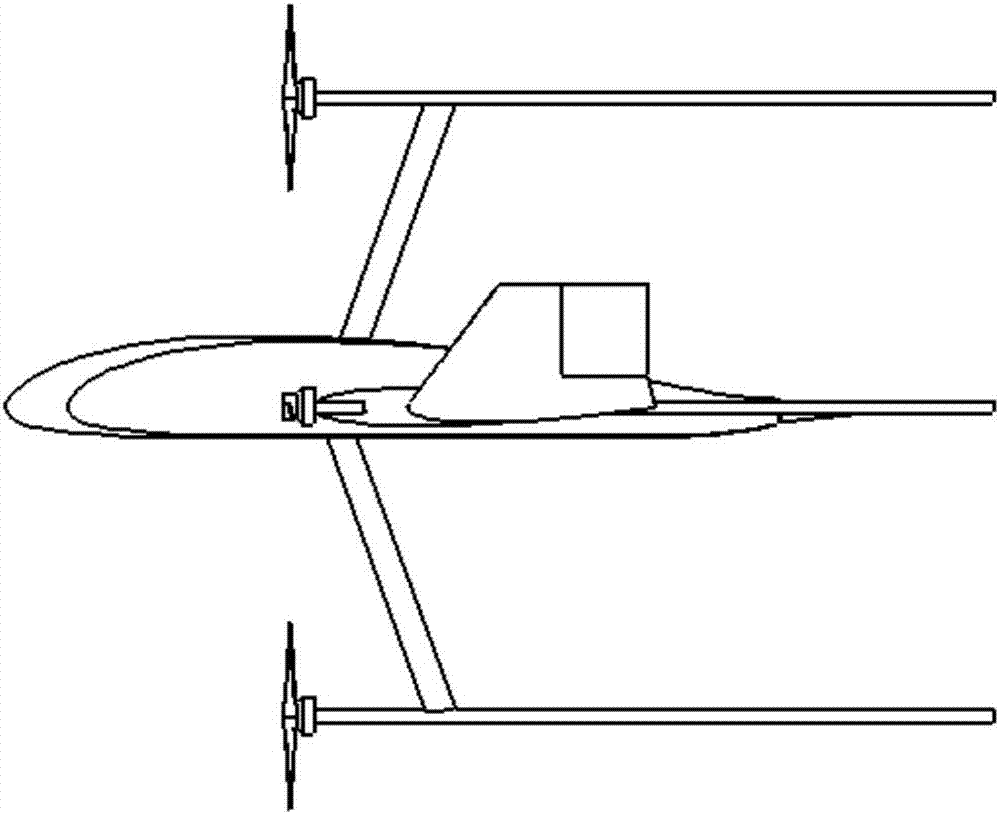
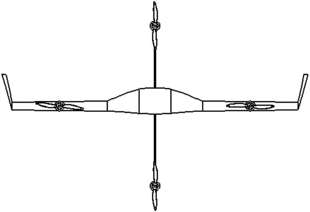
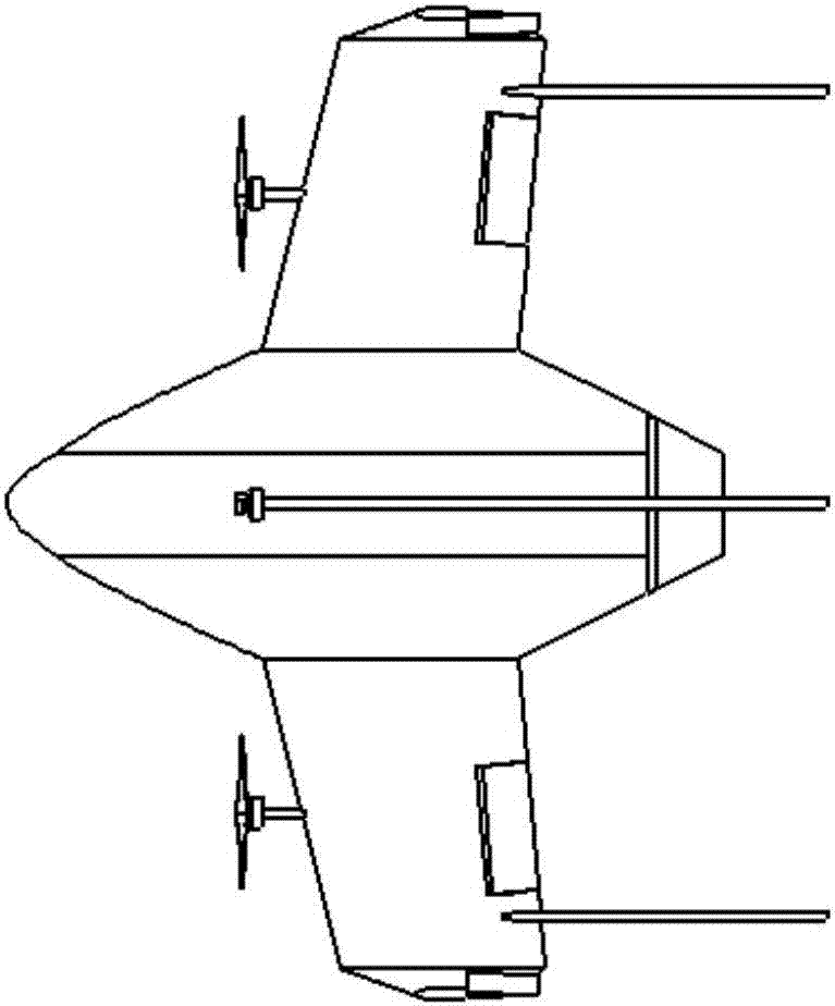
[0004] In order to overcome the common problems of low aerodynamic efficiency, complex tilting mechanism, short flight time, low flight speed, and complex mode conversion in the existing vertical take-off and landing UAV technology, this invention proposes a new concept tailstock type for the first time. Vertical take-off and landing unmanned aerial vehicle and its control method

Method used


Image

  • Vertical take-off and landing unmanned aerial vehicle and control method thereof
  • Vertical take-off and landing unmanned aerial vehicle and control method thereof
  • Vertical take-off and landing unmanned aerial vehicle and control method thereof

Examples


Embodiment Construction

[0026] Embodiments of the present invention are described in detail below, examples of which are shown in the drawings, wherein the same or similar reference numerals designate the same or similar elements or elements having the same or similar functions throughout. The embodiments described below by referring to the figures are exemplary and are intended to explain the present invention and should not be construed as limiting the present invention.

[0027]In describing the present invention, it should be understood that the terms "center", "longitudinal", "transverse", "length", "width", "thickness", "upper", "lower", "front", " Orientation indicated by rear, left, right, vertical, horizontal, top, bottom, inside, outside, clockwise, counterclockwise, etc. The positional relationship is based on the orientation or positional relationship shown in the drawings, which is only for the convenience of describing the present invention and simplifying the description, rather than i...


PUM


Abstract

The invention provides a vertical take-off and landing unmanned aerial vehicle and a control method thereof. A vehicle body of the unmanned aerial vehicle adopts aerodynamic layout of high lift-drag ratio class flying wings, and four motors and propellers are installed on the vehicle body in a mode of cross-shaped arrangement. An elevating control torque is formed by the thrust difference generated by the upper propeller and the lower propeller of the vehicle body, a yaw control torque is formed by the thrust difference generated by the left propeller and the right propeller of the vehicle body, and through the roll control torque formed by the different rotating speeds of the four propellers, the attitude control of the vehicle body of the unmanned aerial vehicle is conducted so that vertical take-off and landing in a narrow region and spot hover at any positions in the flying process of the unmanned aerial vehicle can be achieved. After the unmanned aerial vehicle is switched into a flat flying state, the vehicle body of the class flying wing layout can generate a large cruise lift-drag ratio, the effective loading level of the unmanned aerial vehicle is greatly improved, and the flying distance of the unmanned aerial vehicle is greatly prolonged. When the unmanned aerial vehicle horizontally flies, propelling can be conducted for low-speed flying only by using the left propeller and the right propeller, and propelling can be conducted for high-speed flying by simultaneously using the four propellers.

Description

technical field [0001] The invention relates to the technical field of unmanned aircraft, in particular to a vertical take-off and landing unmanned aerial vehicle and a control method thereof. Background technique [0002] Vertical take-off and landing drones have great application prospects due to their small requirements for take-off and landing sites. The existing UAVs realize vertical take-off and landing mainly through the following forms: one is to use multi-rotors (such as quad-rotor UAVs) to achieve vertical take-off and landing. The second is to use the rotor helicopter to achieve vertical take-off and landing. This method requires a large-power main rotor system. In order to balance the torque generated by the rotor, a specially designed tail rotor or coaxial rotor system is required, and the overall structure is complex. , the body has more degrees of freedom, and flight control is difficult; the third is to use a tilting rotor (such as the American V-22 aircraft...

Claims


Application Information

Patent Timeline
IPC IPC(8): B64C27/28B64C29/02
CPCB64C27/28B64C29/02B64U10/25B64U70/80B64U30/20B64U50/14
Inventor 王文正陈功陆艳辉
Owner 王文正
Learn More