Sludge dewatering equipment

A sludge dewatering and equipment technology, applied in water/sludge/sewage treatment, sludge treatment, dehydration/drying/concentrated sludge treatment, etc. material box and other problems to achieve the effect of complete dehydration

Inactive Publication Date: 2017-06-27
林安益
View PDF0 Cites 13 Cited by
  • Summary
  • Abstract
  • Description
  • Claims
  • Application Information

AI Technical Summary

Problems solved by technology

[0006] In order to overcome the disadvantages of incomplete sludge dehydration, unbreakable sludge before compression, unreplaceable pressure plate and unbeatable feed box in the prior art, the technical problem t

Method used


Image

  • Sludge dewatering equipment
  • Sludge dewatering equipment
  • Sludge dewatering equipment

Examples


Embodiment 1

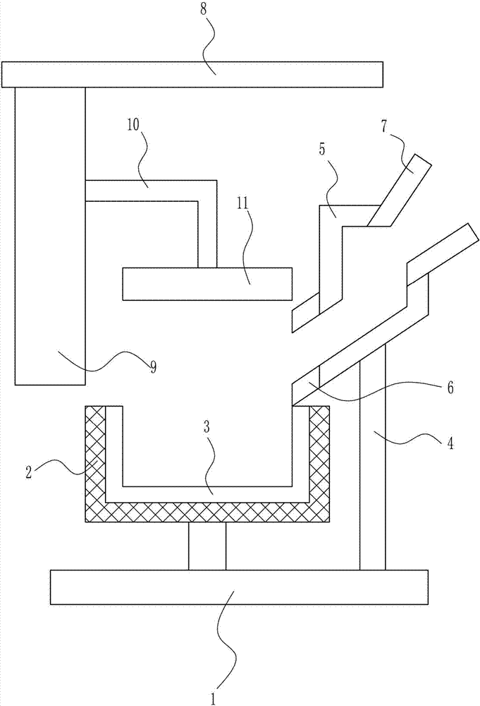
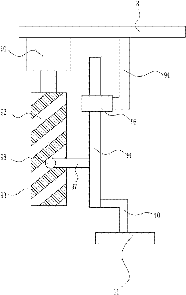
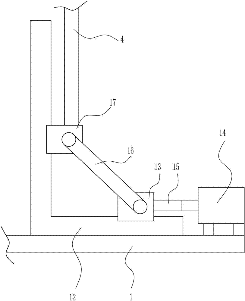
[0040] A kind of sludge dewatering equipment, such as Figure 1-7 As shown, it includes a bottom plate 1, a filter frame 2, a filter membrane 3, a support 4, a feed box 5, a first feed hopper 6, a second feed hopper 7, a top plate 8, a lifting mechanism 9, and a first connecting rod 10 And pressing plate 11, bottom plate 1 top left side is connected with filter frame 2, filter frame 2 is provided with filter membrane 3, bottom plate 1 top right side is connected with support 4, support 4 top is connected with feed box 5, feed box 5 bottom The left side is connected with the first feed hopper 6, the first feed hopper 6 is located above the right side of the filter frame 2, the top right side of the feed box 5 is connected with the second feed hopper 7, and the bottom left side of the top plate 8 is connected with a lifting mechanism 9. The right side of the lifting mechanism 9 is provided with a first connecting rod 10 , the bottom of the first connecting rod 10 is connected wi...

Embodiment 2

[0042] A kind of sludge dewatering equipment, such as Figure 1-7 As shown, it includes a bottom plate 1, a filter frame 2, a filter membrane 3, a support 4, a feed box 5, a first feed hopper 6, a second feed hopper 7, a top plate 8, a lifting mechanism 9, and a first connecting rod 10 And pressing plate 11, bottom plate 1 top left side is connected with filter frame 2, filter frame 2 is provided with filter membrane 3, bottom plate 1 top right side is connected with support 4, support 4 top is connected with feed box 5, feed box 5 bottom The left side is connected with the first feed hopper 6, the first feed hopper 6 is located above the right side of the filter frame 2, the top right side of the feed box 5 is connected with the second feed hopper 7, and the bottom left side of the top plate 8 is connected with a lifting mechanism 9. The right side of the lifting mechanism 9 is provided with a first connecting rod 10 , the bottom of the first connecting rod 10 is connected wi...

Embodiment 3

[0045] A kind of sludge dewatering equipment, such as Figure 1-7 As shown, it includes a bottom plate 1, a filter frame 2, a filter membrane 3, a support 4, a feed box 5, a first feed hopper 6, a second feed hopper 7, a top plate 8, a lifting mechanism 9, and a first connecting rod 10 And pressing plate 11, bottom plate 1 top left side is connected with filter frame 2, filter frame 2 is provided with filter membrane 3, bottom plate 1 top right side is connected with support 4, support 4 top is connected with feed box 5, feed box 5 bottom The left side is connected with the first feed hopper 6, the first feed hopper 6 is located above the right side of the filter frame 2, the top right side of the feed box 5 is connected with the second feed hopper 7, and the bottom left side of the top plate 8 is connected with a lifting mechanism 9. The right side of the lifting mechanism 9 is provided with a first connecting rod 10 , the bottom of the first connecting rod 10 is connected wi...


PUM


Abstract

The invention relates to a dewatering device, in particular to a sludge dewatering device. The technical problem to be solved by the present invention is to provide a sludge dehydration equipment which can thoroughly dewater sludge, crush the sludge before compression, replace the pressing plate and beat the feed box. In order to solve the above technical problems, the present invention provides such a sludge dewatering equipment, which includes a bottom plate, a filter frame, a filter membrane, a bracket, a feed box, a first feed hopper, a second feed hopper, etc.; The side is connected with a filter frame, the filter frame is provided with a filter membrane, the top right side of the bottom plate is connected with a support, the top of the support is connected with a feed box, and the left side of the bottom of the feed box is connected with a first feed hopper, the first feed hopper is located at Above the right side of the filter frame, a second feed hopper is connected to the top right side of the feed box. The present invention designs a sludge dewatering device, which moves the pressure plate up and down by starting the first motor to rotate clockwise and counterclockwise, so that the sludge in the filter frame can be squeezed powerfully.

Description

technical field [0001] The invention relates to a dewatering device, in particular to a sludge dewatering device. Background technique [0002] Sludge is the solid sedimentation material produced by water and wastewater treatment processes. [0003] The existing sludge dewatering equipment uses the motor to drive the pulley to push the pressure plate to dehydrate the sludge, which cannot effectively compress the sludge effectively, and the sludge dehydration is not so thorough, and there are many sludges in the sludge. Impurities, there are also relatively hard impurities, which will hinder the compression of the sludge by the press plate, resulting in incomplete compression of the sludge, and the dehydration effect will not be so good. During the process of compressing the sludge, the press plate is easy to Pollutants stuck to the sludge, if the pressure plate is not cleaned or replaced in time, the pressure plate will undergo chemical changes with the sludge, resulting in...

Claims


Application Information

Patent Timeline
IPC IPC(8): C02F11/12B01D33/15B01D33/72
CPCC02F11/122B01D33/15B01D33/72C02F11/127
Inventor 林安益
Owner 林安益
Why Eureka
Try Eureka