Two-stage main spring type non-equal offset frequency type gradually-changed severity leaf spring stress intensity checking method

A technology of stress intensity and main spring, which is applied to spring components, springs, leaf springs, etc. composed of several springs, can solve the problem of complicated stress intensity checking, failure to meet design requirements, and failure to provide a two-stage main spring type. Non-equi-offset frequency gradient stiffness leaf spring and other problems, to achieve the effect of reducing design and test costs, speeding up product development, and improving product design level

Active Publication Date: 2017-06-27
山东恒日悬架弹簧股份有限公司
View PDF5 Cites 0 Cited by
  • Summary
  • Abstract
  • Description
  • Claims
  • Application Information

AI Technical Summary

Problems solved by technology

However, due to the fact that the stress intensity check of the two-stage main spring type non-equal bias frequency gradient stiffness leaf spring is very complicated, it is not only related to the leaf spring structure, load size and allowable stress, but also related to the contact load and the thickness of the leaf spring with the largest thickness. At the same time, it is also restricted by the calculation of the equivalent thickness of the overlapping parts of the leaf springs at all levels. According to the research data, it has not been possible to give the calibration of the stress intensity of the two-stage main spring type non-equal deviation frequency type gradient stiffness leaf spring before. Nuclear methods are mostly determined through experimental tests, so they cannot meet the rapid development of the vehicle industry and the modern CAD design requirements of suspension springs

Method used


Image

  • Two-stage main spring type non-equal offset frequency type gradually-changed severity leaf spring stress intensity checking method
  • Two-stage main spring type non-equal offset frequency type gradually-changed severity leaf spring stress intensity checking method
  • Two-stage main spring type non-equal offset frequency type gradually-changed severity leaf spring stress intensity checking method

Examples


Embodiment

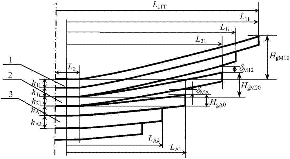
[0039] Embodiment: The width b of a certain two-stage main spring type unequal-bias frequency gradual stiffness leaf spring is 63 mm, half of the clamping distance of the saddle bolt L 0 = 50mm. Number of primary reeds n 1 = 2, the thickness h of each piece of the first stage main spring 11 =h 12 =8mm, half of the working length of each leaf of the first stage main spring is L respectively 11T =525mm,L 12T =450mm; half of the clamping length is L 11 = L 11T -L 0 / 2=500mm, L 12 = L 12T -L 0 / 2=425mm. Second stage main reed number n 2 = 1, thickness h 21 =8mm, half the working length L 21T =350mm, half of the clamping length L 21 = L 21T -L 0 / 2=325mm. The number of secondary reeds m = 2, the thickness of each secondary reed h A1 =h A2 =13mm; half of the working length of each piece of auxiliary spring is L A1T =250mm,L A2T =150mm; the clamping length of half of each leaf of secondary spring is L A1 = L A1T -L 0 / 2=225mm, L A2 = L A2T -L 0 / 2=125mm. T...


PUM


Abstract

The invention relates to a two-stage main spring type non-equal offset frequency type gradually-changed severity leaf spring stress intensity checking method, and belongs to the technical field of suspension steel plate springs. According to structure parameters of a first-stage main spring, a second-stage main spring and an auxiliary spring, the u-bolt clamping distance, starting contact loads of all times, the maximum load and the allowable stress, on the basis of maximum stress calculation of root parts of all leaf springs, and the stress strength of the two-stage main spring type non-equal offset frequency type gradually-changed severity leaf springs is checked. Through a model machine loading stress test, it is known that the two-stage main spring type non-equal offset frequency type gradually-changed severity leaf spring stress intensity checking method is right, and reliable technological method is provided for leaf spring strength checking and CAD software developing. By means of the method, the leaf spring stress strength design requirement can be guaranteed, and the product design level, quality and reliability and the vehicle travelling safety are improved; and meanwhile, the design and test cost can be reduced, and the product developing speed is increased.

Description

technical field [0001] The invention relates to a vehicle suspension leaf spring, in particular to a method for checking the stress intensity of a two-stage main spring type non-equal bias frequency type gradient stiffness leaf spring. Background technique [0002] In order to further improve the ride comfort of the vehicle under half-load conditions, a two-stage main spring type gradient stiffness leaf spring can be used, that is, the main spring of the original one-stage gradient stiffness leaf spring is split into two-stage main springs; at the same time, in order to ensure that the main spring The stress intensity of the spring, usually through the initial tangent arc height of the first-stage main spring, the second-stage main spring and the auxiliary spring, and the two-stage gradual change gap, so that the second-stage main spring and the auxiliary spring can properly bear the load in advance, thereby reducing the first-stage The stress of the main spring, that is, th...

Claims


Application Information

Patent Timeline
Patent Type & Authority Applications(China)
IPC IPC(8): F16F1/18F16F1/22F16F3/02G06F17/50
CPCF16F1/185F16F1/22F16F3/023G06F30/15G06F2119/06G06F2119/18
Inventor 王炳超周长城
Owner 山东恒日悬架弹簧股份有限公司
Why Eureka
Try Eureka