

Signal sending method and device
A technology of signal transmission and signal transmission, which is applied in the field of communication, can solve the problems of high hardware cost, high complexity of equipment at the transmitting end and receiving end, and achieve the effect of saving hardware cost, reducing equipment complexity, and optimizing the wireless communication system
- Summary
- Abstract
- Description
- Claims
- Application Information
AI Technical Summary
Problems solved by technology
Method used
Image


Examples
Embodiment 1
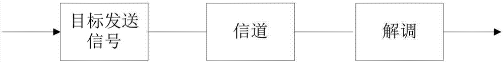
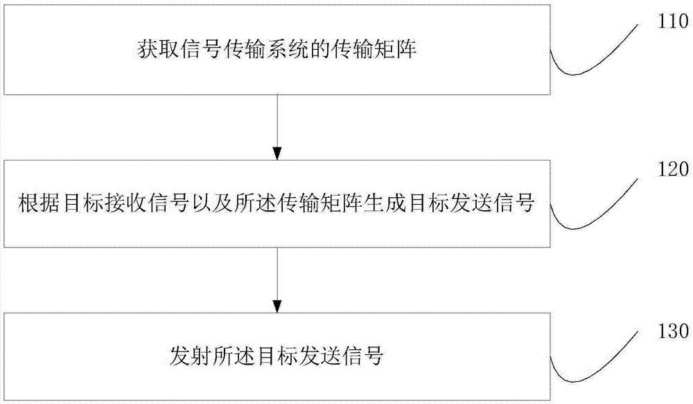
[0033] image 3 This is a flow chart of a signal sending method provided in Embodiment 1 of the present invention. This embodiment is applicable to a situation where a signal is sent by a sending end. The method can be executed by a signal sending end of a wireless communication system and specifically includes the following steps:
[0034] Step 110: Obtain a transmission matrix of the signal transmission system.
[0035] The wireless channel is the signal transmission medium in the wireless communication system, and the channel characteristics of the wireless channel are described by the transmission matrix. In this embodiment, the transmission matrix of the signal transmission system specifically refers to the transmission matrix of the actual channel.
[0036] At present, there are many ways to obtain the channel transmission matrix. Typically, the transmission matrix of the signal transmission system can be obtained through the channel estimation method. The preferred channel est...
Embodiment 2
[0046] Figure 4 This is a flowchart of a signal sending method provided in the second embodiment of the present invention. This embodiment is based on the first embodiment, and both steps 110 and 120 of the first embodiment are optimized, which specifically includes the following steps:
[0047] Step 210: Use the M transmitting antennas in the signal transmission system to transmit pilot signals.
[0048] In this embodiment, in order to determine the transmission matrix of the wireless communication system, the transmission coefficient h between each transmitting and receiving antenna needs to be calculated separately. For example, if the wireless communication system includes two transmitting antennas and one receiving antenna, the calculation is required The transmission matrix H is [h 11 , H 12 ], where h 11 Is the transmission coefficient between the first transmitting antenna and the receiving wire, h 12 Is the transmission coefficient between the second transmitting antenna a...
Embodiment 3
[0061] Figure 5 This is a flowchart of a signal receiving method provided in the third embodiment of the present invention. This embodiment is applicable to a situation where the receiving end receives a signal. The method can be executed by a signal receiving device of a wireless communication system, and specifically includes the following steps:
[0062] Step 310: Receive the target transmission signal transmitted through the signal transmission system through at least one receiving antenna, where the target transmission signal is generated according to the transmission matrix of the signal transmission system and the target reception signal.
[0063] When the transmitting antenna transmits the target transmission signal, the target transmission signal can be received by the receiving antenna after being transmitted through the wireless channel in the signal transmission system. The target transmission signal is generated according to the transmission matrix of the signal transm...
PUM
 Abstract
Description
Claims
Application Information