Discrete bioelectrical impedance identification device

A bioelectrical impedance and identification device technology, applied in the field of medical devices, can solve the problems of increasing the cost of surgery, waste, and radiation damage to patients, and achieve the effects of improving the success rate of surgery, reducing the cost of use, and saving surgery time.

Inactive Publication Date: 2017-06-30
BEIJING SMTP TECH CO LTD
View PDF7 Cites 3 Cited by
  • Summary
  • Abstract
  • Description
  • Claims
  • Application Information

AI Technical Summary

Problems solved by technology

[0002] In the prior art, in surgical operations, especially spinal surgery and neurosurgery, it is necessary to fix the spine after laminectomy, and the built-in screws used in the fixation need to be driven into the vertebral body along the pedicle by the doctor. This kind of operation is generally a blind operation, and its success depends on the experience of the doctor. Medical accidents often occur when the screw is crooked and enters the spinal canal.
[0003] At present, there are two methods of assisting screw observation. One is to use intraoperative X-ray fluoroscopy to observe the position of the screw, but the disadvantage of this observation method is that it will cause radiation damage to the patient and cannot be used frequently; the other is to use evoked potential. The instrument detects the sealing of the screw to the nerve root, and then judges whether the direction of the screw deviates, but its disadvantages are that the preoperative preparation time is long, the measurement accuracy is poor, and the evoked potential equipment is relatively expensive, not all hospital operating rooms standard configuration
[0004] The current identification device based on bioelectrical impedance technology can effectively avoid the shortcomings of the above two methods, and is faster and safer, but most of the current products are designed as a whole. figure 1 As shown, since the device is a battery-powered electronic device, it is not easy to clean and sterilize the product after use, so it can only be a disposable product, which not only causes a lot of waste, but also increases the cost of the operation

Method used


Image

  • Discrete bioelectrical impedance identification device
  • Discrete bioelectrical impedance identification device
  • Discrete bioelectrical impedance identification device

Examples


Embodiment Construction

[0037] In order to make the objectives, technical solutions, and advantages of the present invention clearer, the present invention will be further described in detail below in conjunction with specific embodiments and with reference to the accompanying drawings. It should be understood that these descriptions are only exemplary and not intended to limit the scope of the present invention. In addition, in the following description, descriptions of well-known structures and technologies are omitted to avoid unnecessarily obscuring the concept of the present invention.

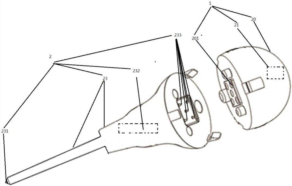
[0038] See figure 2 , figure 2 It is a schematic diagram of the structure of the discrete bioelectrical impedance recognition device provided by the first embodiment of the present invention.

[0039] Such as figure 2 As shown, the present invention provides a discrete bioelectrical impedance recognition device, including: a control module 1 and a detection module 2. The control module 1 and the detection module ...


PUM


Abstract

The invention discloses a discrete bioelectrical impedance identification device, which comprises a control module and a detection module, wherein the control module comprises a control shell and a control processing circuit arranged in the control shell; the control shell is provided with conductive sheets which are partially exposed out of the control shell; the conductive sheets are electrically connected with the control processing circuit; the detection module comprises a detection shell, a probe embedded into one end of the detection shell and a power supply embedded into the other end of the detection shell. When the control shell is fixedly connected with the detection shell, a conductive needle group props against the conductive sheets; and when the control shell is separated from the detection shell, the conductive needle group is separated from the conductive sheets. Compared with an integral bioelectrical impedance identification device in the prior art, on one hand, the utilization rate of a product is improved and the use cost is reduced; and on the other hand, waste is avoided and the product is more environment-friendly.

Description

Technical field [0001] The invention relates to the technical field of medical devices, and in particular to a discrete bioelectrical impedance recognition device. Background technique [0002] In the prior art, in surgical operations, especially spinal surgery and neurosurgery, it is necessary to fix the spine after laminectomy. The internal screw used in the fixation requires the doctor to drive into the vertebral body along the pedicle. This kind of operation is generally blind operation, and its success depends on the doctor's experience. The screw may enter the spinal canal and cause medical accidents from time to time. [0003] There are currently two ways to assist in observing screws. One is to use intraoperative X-ray fluoroscopy to observe the position of the screw. However, the disadvantage of this observation method is that it can cause radiation damage to the patient and cannot be used frequently; the other is through evoked potentials. The instrument detects the seal...

Claims


Application Information

Patent Timeline
Patent Type & Authority Applications(China)
IPC IPC(8): A61B5/053A61B34/20A61B17/88
CPCA61B5/0536A61B17/88A61B17/90A61B5/063A61B2560/0443A61B5/0538A61B2560/0214
Inventor 沈建雄曹群战松涛
Owner BEIJING SMTP TECH CO LTD
Why Eureka
Try Eureka