Batching efficient stirring device for brake pad production

A stirring device and technology for brake pads, applied in the field of high-efficiency mixing devices for ingredients used in brake pad production, can solve problems such as insufficient and time-consuming stirring

Inactive Publication Date: 2017-06-30
来安县华鹏摩擦材料厂
View PDF4 Cites 8 Cited by
  • Summary
  • Abstract
  • Description
  • Claims
  • Application Information

AI Technical Summary

Problems solved by technology

[0006] In order to overcome the shortcomings of time-consuming and insufficient stirring in the prior art, the technical problem to be solved by the present invention is to provide a high-efficiency stirring device for brake pad production ingredients that saves time and stirs sufficiently

Method used


Image

  • Batching efficient stirring device for brake pad production
  • Batching efficient stirring device for brake pad production
  • Batching efficient stirring device for brake pad production

Examples


Embodiment 1

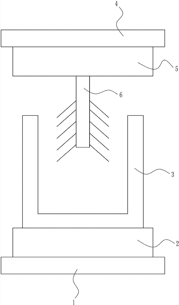
[0040] A high-efficiency mixing device for ingredients used in brake pad production, such as Figure 1-7 As shown, it includes a bottom plate 1, a lifting mechanism 2, a mixing box 3, a top plate 4, a rotating mechanism 5 and a stirring rod 6. The top of the bottom plate 1 is connected with a lifting mechanism 2, and the top of the lifting mechanism 2 is connected with a mixing box 3. The top of the bottom plate 1 is directly above A top plate 4 is provided, a rotating mechanism 5 is connected to the bottom of the top plate 4 , a stirring rod 6 is connected to the bottom of the rotating mechanism 5 , and the stirring rod 6 is located in the stirring box 3 .

Embodiment 2

[0042] A high-efficiency mixing device for ingredients used in brake pad production, such as Figure 1-7 As shown, it includes a bottom plate 1, a lifting mechanism 2, a mixing box 3, a top plate 4, a rotating mechanism 5 and a stirring rod 6. The top of the bottom plate 1 is connected with a lifting mechanism 2, and the top of the lifting mechanism 2 is connected with a mixing box 3. The top of the bottom plate 1 is directly above A top plate 4 is provided, a rotating mechanism 5 is connected to the bottom of the top plate 4 , a stirring rod 6 is connected to the bottom of the rotating mechanism 5 , and the stirring rod 6 is located in the stirring box 3 .

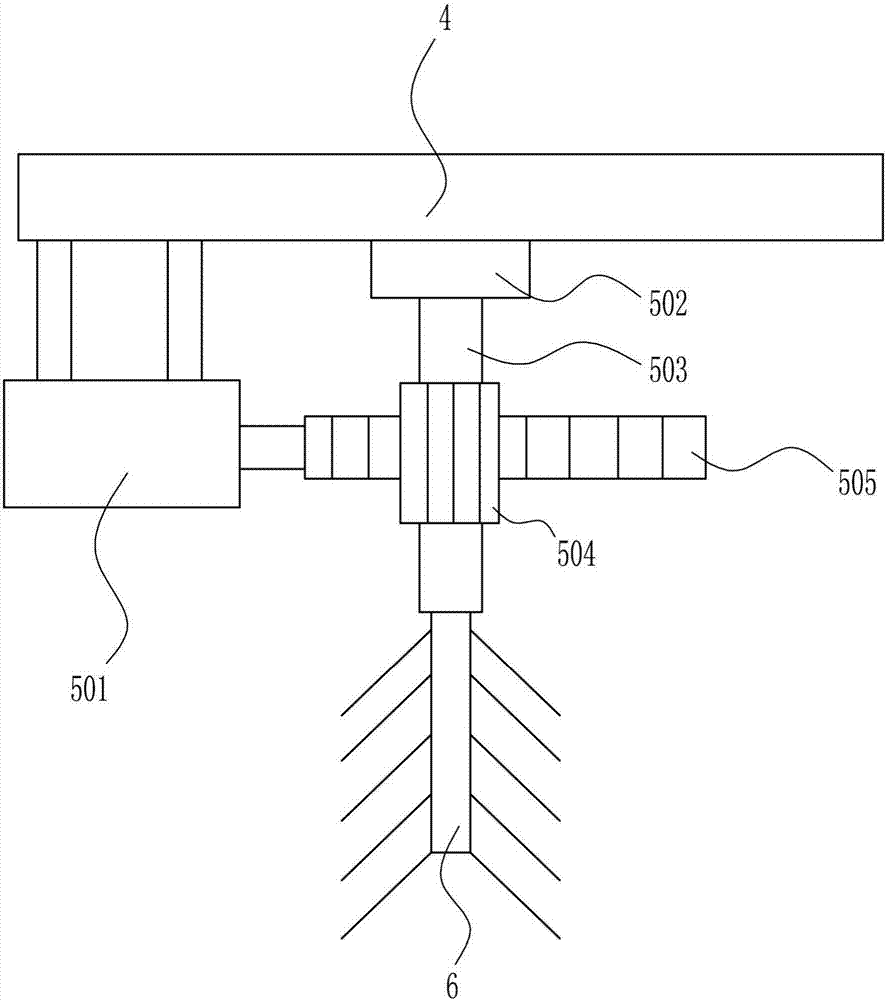
[0043] The rotating mechanism 5 includes an electric push rod 501, a first bearing seat 502, a rotating shaft 503, a gear 504 and a rack 505, the bottom left side of the top plate 4 is connected with an electric push rod 501, and the right side of the electric push rod 501 is connected with a rack 505, The bottom center o...

Embodiment 3

[0045] A high-efficiency mixing device for ingredients used in brake pad production, such as Figure 1-7 As shown, it includes a bottom plate 1, a lifting mechanism 2, a mixing box 3, a top plate 4, a rotating mechanism 5 and a stirring rod 6. The top of the bottom plate 1 is connected with a lifting mechanism 2, and the top of the lifting mechanism 2 is connected with a mixing box 3. The top of the bottom plate 1 is directly above A top plate 4 is provided, a rotating mechanism 5 is connected to the bottom of the top plate 4 , a stirring rod 6 is connected to the bottom of the rotating mechanism 5 , and the stirring rod 6 is located in the stirring box 3 .

[0046] The rotating mechanism 5 includes an electric push rod 501, a first bearing seat 502, a rotating shaft 503, a gear 504 and a rack 505, the bottom left side of the top plate 4 is connected with an electric push rod 501, and the right side of the electric push rod 501 is connected with a rack 505, The bottom center o...


PUM


Abstract

The invention relates to a stirring device, in particular to a batching efficient stirring device for brake pad production. The technical problem to be solved by the invention is to provide the efficient stirring device for stirring brake pads with time saving and full stirring. In order to solve the technical problem, the invention provides the batching efficient stirring device for brake pad production, which comprises a soleplate, etc; a lifting mechanism is connected at the top of the soleplate, a stirring box is connected with the top of the lifting mechanism, a top plate is arranged above the soleplate, the bottom of the top plate is connected with a rotating mechanism; the bottom of the rotating mechanism is connected with a stirring rod; and the stirring rod is positioned in the stirring box. According to the batching efficient stirring device for brake pad production, the arranged stirring rod is subjected to clockwise and anticlockwise rotation to mix the ingredients in the stirring box for the brake pad production.

Description

technical field [0001] The invention relates to a stirring device, in particular to a high-efficiency stirring device for ingredients used in brake pad production. Background technique [0002] Brake pads are also called brake pads. In the braking system of a car, the brake pads are the most critical safety parts. The brake pads play a decisive role in the quality of all braking effects, so good brake pads are the protectors of people and cars. [0003] The production process of the existing ingredients for brake pad production is mostly very simple. The staff pours the ingredients for brake pad production into a container, and then manually stirs the ingredients for brake pad production, so that the ingredients for brake pad production are mixed very unevenly. Moreover, when there are hard objects, manual stirring cannot be handled, and some stirring devices take a lot of time to stir, and it is very time-consuming to achieve the purpose of mixing only by the rotation of a...

Claims


Application Information

Patent Timeline
Patent Type & Authority Applications(China)
IPC IPC(8): B01F11/00B01F7/00
CPCB01F27/171B01F31/56
Inventor 华鹏
Owner 来安县华鹏摩擦材料厂
Why Eureka
Try Eureka