

Micro-turbine disc forming device and method
A micro-turbine and cavity technology, applied in forging/pressing/hammer devices, wheels, transportation and packaging, etc., can solve the problems of micro-parts forging and forming difficulties, achieve improved material flow behavior, high dimensional accuracy, and reduce surface oxidation Effect
Inactive Publication Date: 2017-06-30
HARBIN INST OF TECH AT WEIHAI
View PDF9 Cites 6 Cited by
- Summary
- Abstract
- Description
- Claims
- Application Information
AI Technical Summary
Problems solved by technology
However, the forging of micro parts becomes extremely difficult due to the existence of size effects
Method used
View moreImage
Smart ImageViewing Examples

Examples
specific Embodiment approach 1
[0034] Specific implementation mode one: combine figure 1 with 2 Describe this embodiment, this embodiment takes GH4169 superalloy material as an example to introduce the method for manufacturing the micro-turbine disc structure, and the specific steps are:
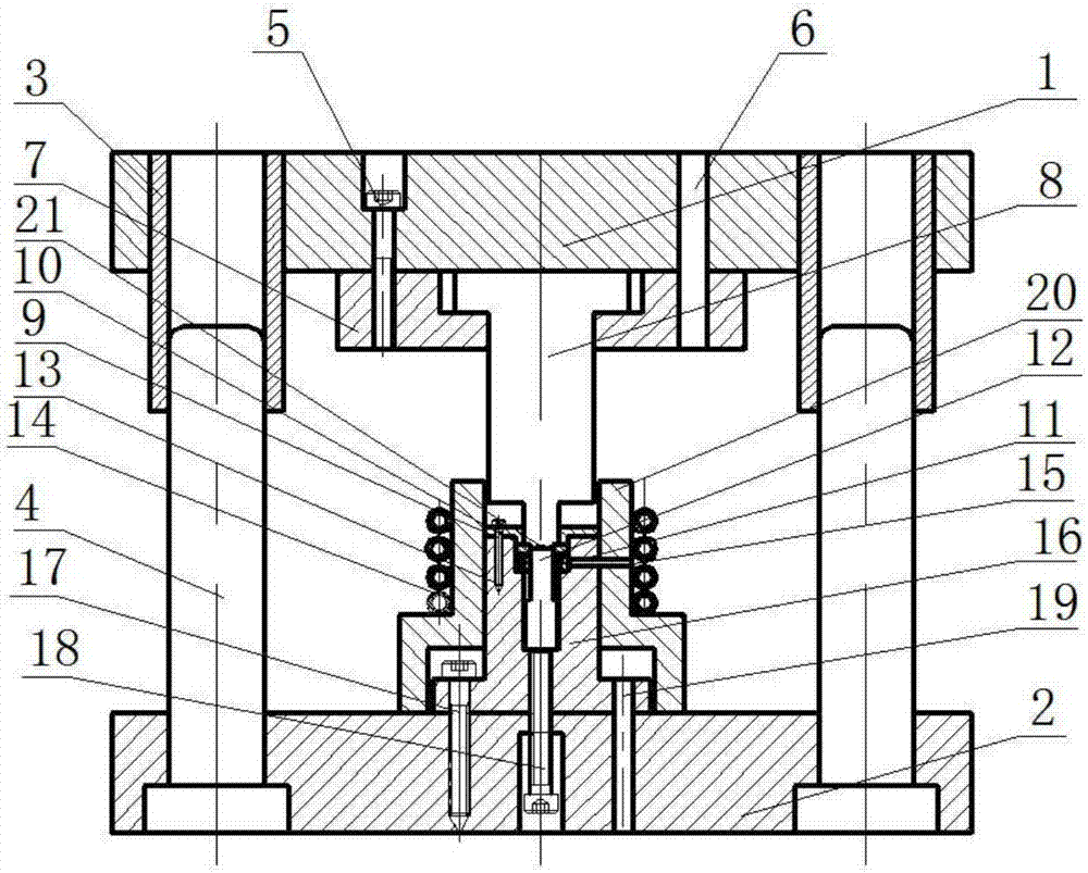
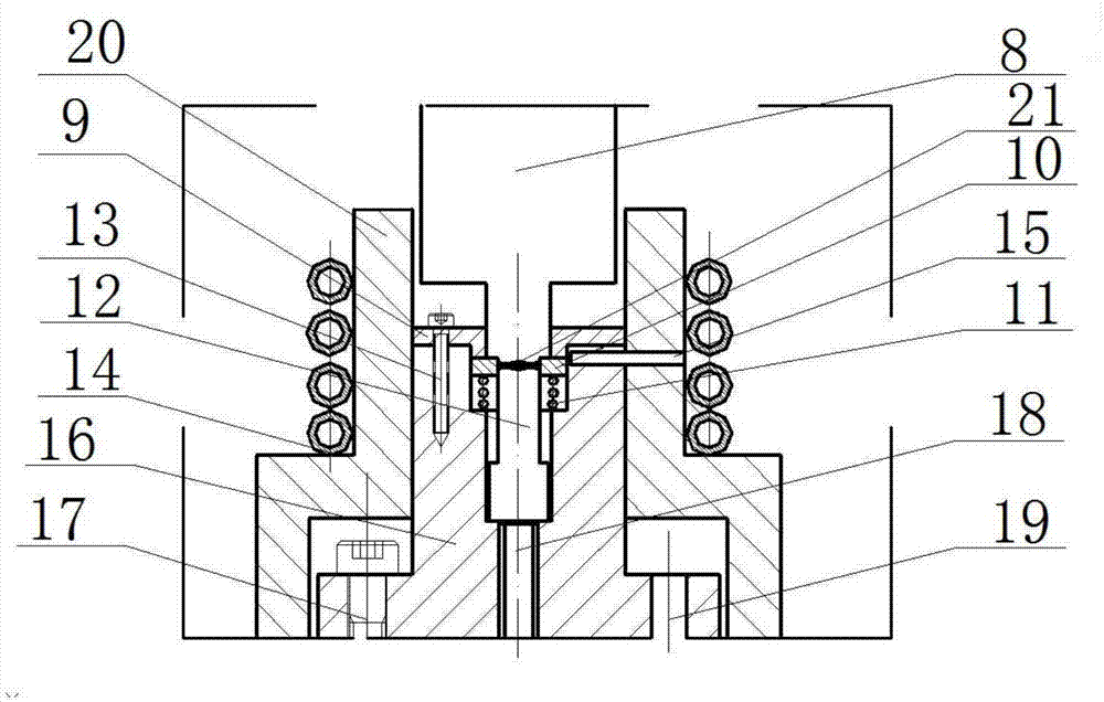
[0035] Step 1: The upper template (1) drives the upper punch (8) up together under the drive of the press, and stops when the upper punch (8) is 5-10 mm away from the upper surface of the die fixing plate (12).
[0036] Step 2: placing the processed blank in the mold cavity formed by the floating die (10) and the lower punch (12);
Login to View More PUM
| Property | Measurement | Unit |
|---|---|---|
| diameter | aaaaa | aaaaa |
| thickness | aaaaa | aaaaa |
| depth | aaaaa | aaaaa |
Abstract
The invention relates to the field of micro-turbine disc precise manufacturing, in particular to a micro-turbine disc forming device and method. The device is characterized in that an upper mold plate (1) and a lower mold plate (2) are arranged; guide sleeves (3) are arranged on the upper mold plate (1); guide columns (4) matched with the guide sleeves (3) are arranged on the lower mold plate (2); a closed frame is formed by the upper mold plate (1) and the lower mold plate (2) through the guide sleeves (3) and the guide columns (4); and a mold auxiliary mechanism is arranged in the closed frame and comprises an upper puncher pin fixing plate (7), an upper puncher pin (8), a concave mold fixing plate (9), a floating concave mold (10), a spring (11), a lower puncher pin (12), an induction coil (14), a concave mold containing cavity (16), an ejection bolt (18) and a ceramic sleeve (20). Compared with the prior art, the device has the beneficial effects of being simple in structure, short in technological process, high in efficiency, low in cost and the like.
Description
technical field [0001] The invention relates to the field of precision manufacturing of micro-turbine discs, in particular to a micro-turbine disc forming device and method. Background technique [0002] Micro-aircraft is one of the most attractive products in the field of aerospace at present, and the miniaturization of the power unit is the key technology of a new type of micro-aircraft with stronger performance and more flexibility. The microjet engine is one of the important micro power devices, its size is roughly 1 / 100~1 / 10 of the ordinary turbine engine, it has the advantages of small size, light weight, portability, and large thrust-to-weight ratio, whether it is for national defense, Military fields such as aerospace and civil fields such as micro-energy, mobile communications, and robots all have huge application potential and bright prospects. The working principle of the micro-turbine engine is the same as that of the traditional gas turbine engine, but the size...
Claims
Login to View More Application Information
Patent Timeline
 Patent Type & AuthorityApplications(China)
IPC IPC(8): B21J1/06B21J5/02B21J13/02B21K1/32
CPCB21J1/06B21J5/025B21J13/02B21K1/32
Inventor王传杰张鹏陈刚郭斌
OwnerHARBIN INST OF TECH AT WEIHAI