Spot-adjustable laser cladding head

A laser cladding and cladding head technology, applied in laser welding equipment, welding equipment, metal processing equipment, etc., can solve the problems of changing the focus point of powder feeding and affecting the quality of cladding

Inactive Publication Date: 2017-06-30
ADVANCED MFG TECH CENT CHINA ACAD OF MASCH SCI & TECH
View PDF5 Cites 2 Cited by
  • Summary
  • Abstract
  • Description
  • Claims
  • Application Information

AI Technical Summary

Problems solved by technology

The current laser cladding head, the adjustment of the spot diameter can only rely on the change of the distance between the laser cladding head and the cladding workpiece, but the

Method used


Image

  • Spot-adjustable laser cladding head

Examples


Example Embodiment

[0020] Example 1: Circular spot cladding.

[0021] The steps are as follows:
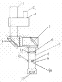
[0022] (1) Rotate the integrator mirror rotation axis 10 so that the integrator mirror 8 is at the side position where the beam does not pass;

[0023] (2) According to the actual cladding requirements, turn on the focusing lens lock switch 11 and adjust the position of the focusing lens 6 in the cladding head body 7 until the best spot diameter is obtained. If it is necessary to obtain a cladding spot with a smaller diameter, the focusing lens 6 is placed at the upper position of the main body 7 of the cladding head; if a cladding spot with a larger diameter needs to be obtained, the focusing lens 6 is placed on the main body 7 of the cladding head. Lower position

[0024] (3) Turn off the focus lens lock switch 11, so that the focus lens 6 is fixed at a certain position in the main body 7 of the cladding head.

Example Embodiment

[0025] Embodiment 2: Rectangular spot cladding.

[0026] The steps are as follows:

[0027] (1) Rotate the rotating shaft 10 of the integrator mirror so that the integrator mirror 8 is in the center position where the light beam passes;

[0028] (2) According to the actual cladding needs, turn on the focus lens lock switch 11 and adjust the position of the focus lens 6 in the cladding head body 7 until the best spot diameter is obtained; you can also turn on the integrator lock switch 12 , Adjust the position of the integrator 8 in the main body 7 of the cladding head, until the best spot diameter is obtained;

[0029] (3) Turn off the focus lens lock switch 11 (or the integrator lens lock switch 12), so that the focus lens 6 (or the integrator lens 8) is fixed to a certain position in the main body 7 of the cladding head.


PUM


Abstract

The invention provides a spot-adjustable laser cladding head. The laser cladding head mainly comprises a laser channel, a reflection mirror, a retroreflector and a cladding head main body, and is characterized by further comprising main components such as a focusing mirror, an integral mirror, an integral mirror fixing bracket, an integral mirror rotating shaft, a focusing mirror locking switch and an integral mirror locking switch and the like. According to the spot-adjustable laser cladding head, the position of the focusing mirror in the cladding head main body can be changed, so that the size of the cladding spot can be changed; the shape of the cladding spot can be changed by moving the integral mirror.

Description

technical field [0001] The invention relates to the field of laser cladding, in particular to a laser cladding head with adjustable light spot. Background technique [0002] During the laser cladding process, when the laser power, scanning speed and powder feeding rate are constant, as the spot diameter increases, the laser specific energy will gradually decrease, while the crack rate of the cladding layer will gradually increase, and the cracking tendency will increase. But on the other hand, as the diameter of the laser spot increases, the number of cladding passes will be reduced, the cladding energy will be homogenized, the dilution rate of the cladding layer will be reduced, the hardness of the cladding layer will be increased, and the surface quality of the cladding layer will be improved; Moreover, as the diameter of the laser spot increases, the cladding rate can also be increased. Therefore, in the laser cladding process, different optimal spot diameters should be ...

Claims


Application Information

Patent Timeline
IPC IPC(8): B23K26/342B23K26/064B23K26/073
CPCB23K26/342B23K26/064B23K26/0643B23K26/0648B23K26/073
Inventor 单忠德孙福臻曲文峰
Owner ADVANCED MFG TECH CENT CHINA ACAD OF MASCH SCI & TECH
Why Eureka
Try Eureka