Eureka AIR delivers breakthrough ideas for toughest innovation challenges, trusted by R&D personnel around the world.

Online sampling method for oil pipeline

A technology for oil pipelines and main pipelines, which is applied in the field of quality inspection and pipeline sampling systems. It can solve problems affecting normal oil transportation, sampling pump failure and damage, and no mixing device, etc., and achieves standardized pipeline construction and operation management. The effect of precise control and precise system control

Inactive Publication Date: 2017-06-30
BC P INC CHINA NAT PETROLEUM CORP +1
View PDF10 Cites 6 Cited by
  • Summary
  • Abstract
  • Description
  • Claims
  • Application Information

AI Technical Summary

Problems solved by technology

[0003] The disadvantages of this sampling method are: 1. There is no mixing device, which cannot ensure that the liquid in the pipeline is fully mixed, and the samples obtained may not be representative
2. Without a sampling control system, it is impossible to monitor the equipment status, power supply, sampling loop flow rate, and sampling frequency of the sampling system
3. The flow measurement of the sampling circuit is not carried out, and it is impossible to judge whether the liquid flow in the sampling circuit is normal
4. Due to the low cleanliness of the pipeline medium, the impurities contained in it often block the sampling pump, resulting in failure and damage of the sampling pump, so that continuous online sampling cannot be realized
5. The pump outlet pipeline is prone to backflow
6. Manual sampling device is not installed, and sampling cannot be performed due to system failure
7. There is no backup circuit, and the system fails to affect the normal oil delivery
11. The flow control is not realized, and the flow of the sampling circuit cannot follow the flow of the main pipeline.
12. The unrealized sampling rate and sample quantity are proportional to the flow rate in the main pipeline

Method used


Image

  • Online sampling method for oil pipeline

Examples


Embodiment Construction

[0036] In order to make the object, technical solution and advantages of the present invention more clear, the present invention will be further described in detail below in conjunction with the accompanying drawings and embodiments. It should be understood that the specific embodiments described here are only used to explain the present invention, not to limit the present invention.

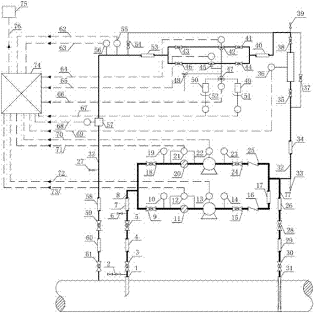
[0037] The online sampling device used in the oil pipeline online sampling method of the present invention, such as figure 1 As shown, a section of bypass 8 is provided on the main pipeline, the inlet of the bypass 8 is connected to the sampling probe 1, the bypass 8 is provided with a sampling pump, and the outlet of the sampling pump is connected to the sampling circuit 32 and the injection circuit 77 , the outlet of the injection circuit 8 is connected to the nozzle 31, and both the sampling probe 1 and the nozzle 31 are connected to the main pipeline.

[0038] Wherein, the sampling probe 1 ...


PUM


Abstract

The invention relates to an online sampling method for an oil pipeline. The online sampling method comprises following steps: 1), a section of bypass pipeline is arranged on a main pipeline, and a liquid enters the bypass pipeline through a sampling probe; 2), pressure detection is performed; 3), filtering and pollution discharge are performed; 4), pressure difference detection is performed at two ends of a filter; 5), the liquid is pressurized by a sampling pump; 6), pressure detection is performed; 7), an outlet of the sampling pump is connected with a sampling loop and a jet loop, the liquid at an outlet end of the jet loop is sprayed into the main pipeline through a spray nozzle, and the liquid entering the sampling loop is subjected to follow-up processes continuously; 8), pollution is discharged; 9), online density detection is performed; 10), gas is exhausted; 11), a sample is taken and stored; 12), the residual liquid after the sample is taken is subjected to pressure detection, temperature detection and flow detection sequentially and is finally converged into the main pipeline. According to the online sampling method for the oil pipeline, reliable, real-time and continuous operation, accurate sample quantity and accurate loop flow control can be realized, and the requirements that the obtained sample is representative, the sampling process is automatic and the system control is accurate are met finally.

Description

technical field [0001] The invention relates to an online sampling method for an oil pipeline, belonging to the technical field of quality detection and pipeline sampling systems. Background technique [0002] For the on-line sampling technology of oil pipelines, the traditional methods are manual sampling or bypassing the main oil pipeline, setting sampling pumps and sampling equipment on the bypass, and then leading the bypass back into the main pipeline. [0003] The disadvantages of this sampling method are: 1. There is no mixing device, which cannot ensure that the liquid in the pipeline is fully mixed, and the sample obtained may not be representative. 2. Without a sampling control system, it is impossible to monitor the equipment status of the sampling system, the power supply, the flow rate of the sampling loop, and the sampling frequency. 3. The flow measurement of the sampling circuit is not carried out, and it is impossible to judge whether the liquid flow in the...

Claims


Application Information

Patent Timeline
Patent Type & Authority Applications(China)
IPC IPC(8): G01N1/14G01N33/28
CPCG01N1/14G01N33/2847
Inventor 张博春聂中文陈子赓岳静飞张皓尹明路
Owner BC P INC CHINA NAT PETROLEUM CORP
Why Eureka
Eureka Blog
Learn More