Novel LED lamp capable of realizing multi-angle illumination

An LED light, multi-angle technology, applied in the parts of lighting devices, lighting devices, lighting auxiliary devices, etc., can solve the problems of single function, inconvenient maintenance and cleaning, and no lighting.

Inactive Publication Date: 2017-07-04
南昌叁润科技有限公司
View PDF7 Cites 13 Cited by
  • Summary
  • Abstract
  • Description
  • Claims
  • Application Information

AI Technical Summary

Problems solved by technology

[0006] In order to overcome the shortcomings of the current LED lamps that cannot illuminate a single position when in use, have relatively single functions, and are inconvenient to maintain and clean up, the technical problem to be solved by the present invention is to provide a single position that can be illuminated, with many functions, A new multi-angle LED light for easy maintenance and cleaning

Method used


Image

  • Novel LED lamp capable of realizing multi-angle illumination
  • Novel LED lamp capable of realizing multi-angle illumination
  • Novel LED lamp capable of realizing multi-angle illumination

Examples


Embodiment 1

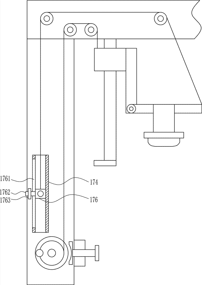
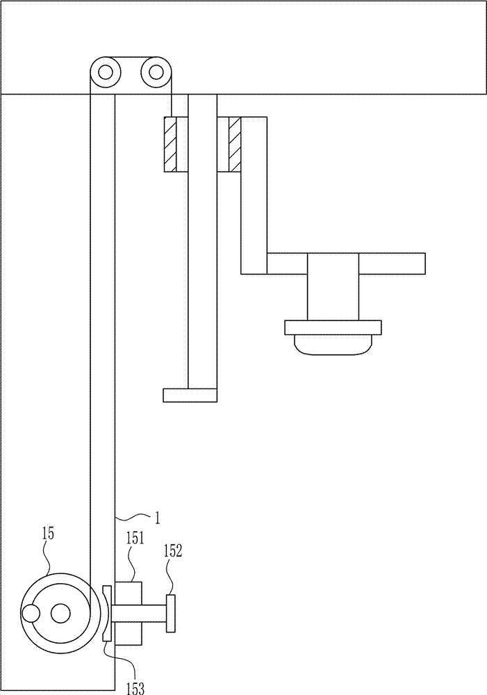
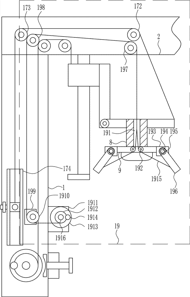
[0037] A new type of LED light that illuminates from multiple angles, such as Figure 1-8 As shown, it includes a fixed plate 1, a mounting plate 2, a guide rail 3, a guide sleeve 4, a block 5, a connecting rod 6, a fixed rod 7, a connecting block 8, a lamp holder 9, a first fixed pulley 10, and a second fixed pulley 11. The first rotating shaft 12, the first reel 13, the first pull wire 14, the first turntable 15 and the first handle 16, the upper side of the fixed plate 1 is installed with the mounting plate 2 by welding, and the lower side of the mounting plate 2 The guide rail 3 is installed on the left by welding, the guide rail 3 is slidably connected with the guide sleeve 4, the lower end of the guide rail 3 is installed with the stopper 5 by welding, and the connecting rod 6 is installed on the right side of the guide sleeve 4 by welding. The lower right side of the connecting rod 6 is installed with a fixed rod 7 by welding, the middle part of the front side of the fi...

Embodiment 2

[0039] A new type of LED light that illuminates from multiple angles, such as Figure 1-8 As shown, it includes a fixed plate 1, a mounting plate 2, a guide rail 3, a guide sleeve 4, a block 5, a connecting rod 6, a fixed rod 7, a connecting block 8, a lamp holder 9, a first fixed pulley 10, and a second fixed pulley 11. The first rotating shaft 12, the first reel 13, the first pull wire 14, the first turntable 15 and the first handle 16, the upper side of the fixed plate 1 is installed with the mounting plate 2 by welding, and the lower side of the mounting plate 2 The guide rail 3 is installed on the left by welding, the guide rail 3 is slidably connected with the guide sleeve 4, the lower end of the guide rail 3 is installed with the stopper 5 by welding, and the connecting rod 6 is installed on the right side of the guide sleeve 4 by welding. The lower right side of the connecting rod 6 is installed with a fixed rod 7 by welding, the middle part of the front side of the fi...

Embodiment 3

[0042] A new type of LED light that illuminates from multiple angles, such as Figure 1-8 As shown, it includes a fixed plate 1, a mounting plate 2, a guide rail 3, a guide sleeve 4, a block 5, a connecting rod 6, a fixed rod 7, a connecting block 8, a lamp holder 9, a first fixed pulley 10, and a second fixed pulley 11. The first rotating shaft 12, the first reel 13, the first pull wire 14, the first turntable 15 and the first handle 16, the upper side of the fixed plate 1 is installed with the mounting plate 2 by welding, and the lower side of the mounting plate 2 The guide rail 3 is installed on the left by welding, the guide rail 3 is slidably connected with the guide sleeve 4, the lower end of the guide rail 3 is installed with the stopper 5 by welding, and the connecting rod 6 is installed on the right side of the guide sleeve 4 by welding. The lower right side of the connecting rod 6 is installed with a fixed rod 7 by welding, the middle part of the front side of the fi...


PUM


Abstract

The invention relates to an LED lamp, in particular to a novel LED lamp capable of realizing multi-angle illumination, and aims to provide the novel LED lamp which can illuminate the single position, has relatively many functions, is convenient to maintain and clean and can realize multi-angle illumination. The novel LED lamp comprises a fixed plate, a mounting plate, a guide rail, a guide sleeve, a stop block, a connecting rod, a fixed rod, a connecting block, a lamp holder, a first fixed pulley, a second fixed pulley, a first rotating shaft and the like; the mounting plate is mounted on the upper side of the fixed plate through welding; the guide rail is mounted on the left side of the lower side of the mounting plate through welding; and the guide sleeve is glidingly connected onto the guide rail. The lamp realizes the effects that the lamp can illuminate the single position, has relatively many functions and is convenient to maintain, the manner that the illuminating position of the LED lamp is controlled through up-and-down movement of a handle is adopted, and more illuminating angles of the LED lamp can be selected.

Description

technical field [0001] The invention relates to an LED lamp, in particular to a novel LED lamp with multi-angle irradiation. Background technique [0002] The basic structure of the LED lamp is an electroluminescent semiconductor material chip, which is cured on the bracket with silver glue or white glue, and then connected to the chip and the circuit board with silver or gold wires, and then sealed with epoxy resin around it. To protect the inner core wire, the shell is finally installed, so the LED lamp has good shock resistance. The field of application involves mobile phones, table lamps, home appliances and other daily household appliances and machinery production. [0003] Most of the current LED lamps can only meet the lighting requirements. If a certain position needs to be illuminated, the traditional LED lamps cannot illuminate a certain position, and the traditional LED lamps need to be illuminated. When repairing and cleaning, users need to climb high to carry ...

Claims


Application Information

Patent Timeline
Patent Type & Authority Applications(China)
IPC IPC(8): F21V21/36F21V21/14F21V14/00F21Y115/10
CPCF21V21/36F21V14/00F21V21/14
Inventor 不公告发明人
Owner 南昌叁润科技有限公司
Why Eureka
Try Eureka