Heat exchange device and heat exchanger

A technology of heat exchange device and heat exchanger, which is applied in the field of heat exchange, and can solve the problems of large installation space and troublesome installation of heat exchangers

Active Publication Date: 2017-07-04
ZHEJIANG SANHUA AUTOMOTIVE COMPONENTS CO LTD
View PDF5 Cites 4 Cited by
  • Summary
  • Abstract
  • Description
  • Claims
  • Application Information

AI Technical Summary

Problems solved by technology

The refrigerant first passes through the expansion valve, resulting in throttling. When it comes out of the valve, it is in a vapor-liquid two-phase state and enters one side of the heat exchanger, and then leaves from the other side of the heat exchanger. Both sides of the heat exchanger need to have connecting pipes , not only the installation is troublesome, but also the installation space required for the heat exchanger is larger

Method used


Image

  • Heat exchange device and heat exchanger
  • Heat exchange device and heat exchanger
  • Heat exchange device and heat exchanger

Examples


Embodiment Construction

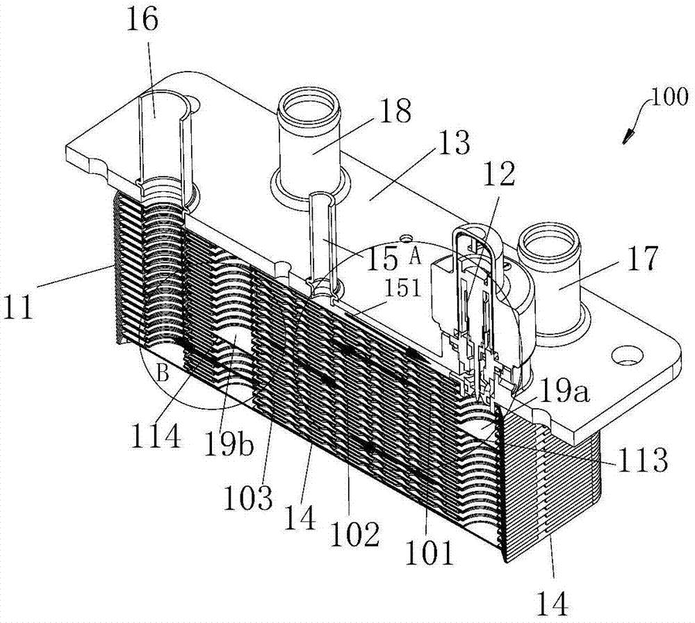
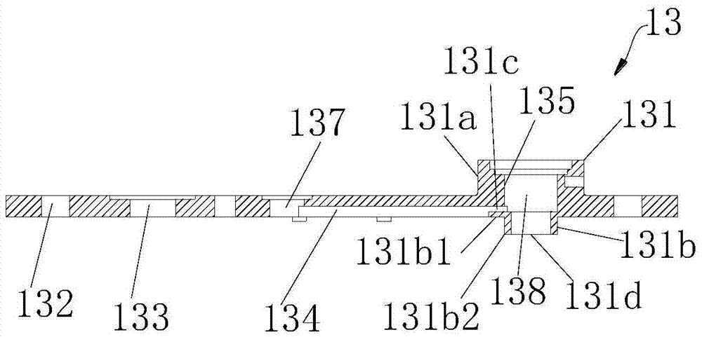
[0046] Reference figure 1 , figure 1 It is a schematic diagram of the three-dimensional structure of an embodiment of the heat exchange device. The heat exchange device 100 includes a heat exchanger core 11, a valve assembly 12, a mounting plate 13, a top plate (not shown), a bottom plate 14, a first outer pipe 15, a second outer pipe 16, a third outer pipe 17, and a fourth outer pipe. Take over 18. The two sides of the heat exchanger core 11 are respectively abutted by the top plate and the bottom plate 14, and the mounting plate 13 abuts against the top plate. Reference figure 2 , The mounting plate 13 includes a plurality of mounting holes 132, a first through hole 137 for fixedly installing the first outer tube 15, a second through hole 133 for fixedly installing the second outer tube 16, and a third outer tube for fixed installation. The third through hole (not shown) of the connecting pipe 17 and the fourth through hole (not shown) for fixing the fourth external pipe 18...


PUM


Abstract

The invention discloses a heat exchange device and a heat exchanger. Plates comprise first plates, second plates and a third plate. The third plate comprises a first blocking portion and a second hole. The first blocking portion corresponds to first holes of all the plates in position. The first holes of the first plates and the second plates are aligned and form a first hole channel. The first hole channel is divided into at least two auxiliary hole channels by the first resisting portion. Each auxiliary hole channel of the first hole channel communicates with the corresponding adjacent auxiliary hole channel through a second hole channel. A first circulation channel is divided into at least two heat exchange sections by the third plate. The flowing directions of fluid in every two adjacent heat exchange section are opposite. A valve assembly is located between a first connector and the first hole channel. A first circulation area of the valve assembly is located outside a heat exchanger core and communicates with the first connector. A second circulation area of the valve assembly communicates with the first hole channel. The heat exchange device and the heat exchanger are small in boundary dimension, so that follow-up installation is convenient, and the heat exchange device and the heat exchanger also have good heat exchange performance.

Description

Technical field [0001] The invention relates to the field of heat exchange technology. Background technique [0002] The battery of an electric car generates heat when it is working and needs to be cooled. Cooling with coolant is a common way. The usual battery cooling device includes a heat exchanger and an expansion valve. The liquid refrigerant enters the heat exchanger through the throttling effect of the expansion valve. After evaporation occurs, the cooling liquid is cooled, and the cooled cooling liquid flows to the battery pack to dissipate the battery. , The temperature of the coolant increases after flowing through the battery pack, and it needs to return to the heat exchanger for cooling. [0003] Usually, the refrigerant flowing through the expansion valve is refrigerant, and the two liquids flowing through the heat exchanger are refrigerant and coolant. The refrigerant first passes through the expansion valve to generate throttling. When it comes out of the valve, it...

Claims


Application Information

Patent Timeline
Patent Type & Authority Applications(China)
IPC IPC(8): F28D9/00H01R13/621H01M10/625H01M10/6567
CPCF28D9/0043H01M10/613H01M10/625H01M10/6567H01M2220/20Y02E60/10
Inventor 不公告发明人
Owner ZHEJIANG SANHUA AUTOMOTIVE COMPONENTS CO LTD
Why Eureka
Try Eureka