
Three-phase magnetic latching relay

A magnetic latching relay, three-phase technology, applied in the direction of electromagnetic relay, relay, detailed information of electromagnetic relay, etc., can solve the problems of insufficient flexibility of mechanism movement, affecting product life, affecting mechanism reliability, etc., to improve movement flexibility and reliability temperature, reduce temperature rise, and balance the effect of thermal field

Active Publication Date: 2017-07-04
XIAMEN HONGFA ELECTRIC POWER CONTROLS
View PDF6 Cites 2 Cited by
  • Summary
  • Abstract
  • Description
  • Claims
  • Application Information

AI Technical Summary

Problems solved by technology

[0004] A three-phase magnetic latching relay in the prior art, as disclosed in Chinese patent CN201112293Y, is to arrange three sets of moving and static spring parts (that is, A phase, B phase, and C phase) in parallel and sequentially on a base. The magnetic circuit part of the three-phase magnetic latching relay is set on the other side of the base. The three-phase magnetic latching relay with this structure is easy to cause the temperature rise of a group of moving and static spring parts (that is, B phase) in the middle. It is obviously higher than the dynamic and static spring parts (ie A phase, C phase) on both sides, thus affecting the life of the product
In addition, in the three-phase magnetic latching relay of the prior art, in the cooperation between the pushing card, the armature part and the moving spring part, the pushing card and the armature part are provided with a limiting structure, and the pushing card and the moving spring part are also provided with a limiting structure. This causes the movement of the mechanism to be not flexible enough, which in turn affects the reliability of the movement of the mechanism

Method used


Image

  • Three-phase magnetic latching relay
  • Three-phase magnetic latching relay
  • Three-phase magnetic latching relay

Examples


Embodiment

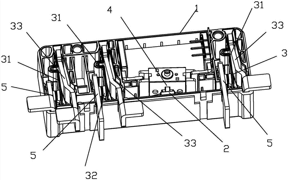
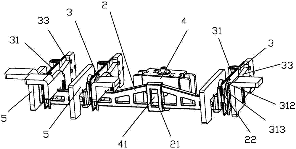
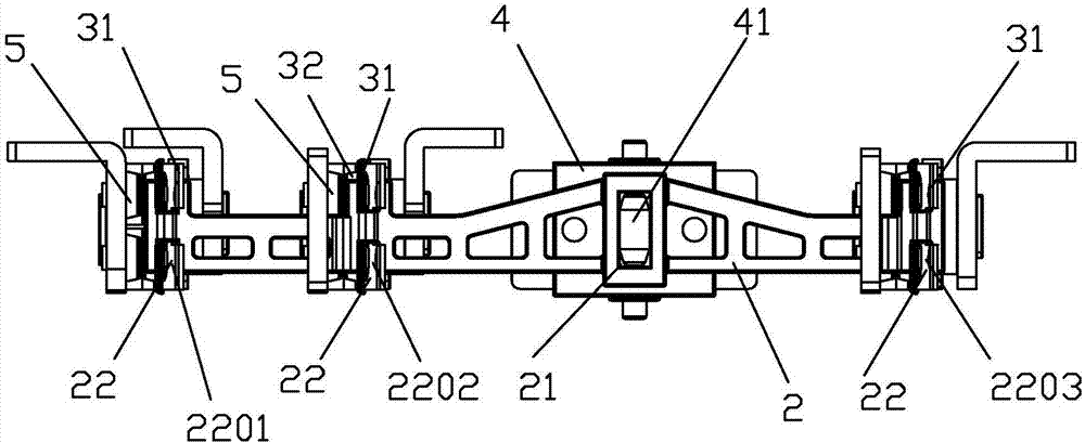
[0034] see Figure 1 to Figure 13As shown, a three-phase magnetic latching relay of the present invention includes a push card 2, an armature part 4, a moving spring part 3 and a base 1, and the armature part 4 and the moving spring part 3 are respectively installed in the base 1; the armature part 4 has a push rod 41; the moving spring part 3 of the present invention has three groups, which are matched with three groups of static spring parts 5; the three groups of moving spring parts are composed of a phase A moving spring part, a B phase moving spring part and a C phase moving spring part , and the A-phase moving spring part, the B-phase moving spring part and the C-phase moving spring part are arranged in sequence in the base; the push rod 41 of the armature part is arranged between the B-phase moving spring part and the C-phase moving spring part; The push card 2 is provided with a first slot 21 for matching with the push rod of the armature part and three second slots 22...


PUM


Abstract

The invention discloses a three-phase magnetic latching relay which comprises a pushing clamp, an armature part, movable spring parts and a base, wherein the movable spring parts consist of an A-phase movable spring part, a B-phase movable spring part and a C-phase movable spring part; a pushing rod of the armature part is arranged between the B-phase movable spring part and the C-phase movable spring part; the pushing clamp is provided with a first clamp groove matched with the pushing rod of the armature part and three second clamp grooves respectively matched with the A-phase movable spring part, the B-phase movable spring part and the C-phase movable spring part; a head of the pushing rod of the armature part is completely suspended in the first clamp groove of the pushing clamp without limiting; and mutual limiting is arranged between the B-phase second clamp groove and the B-phase movable spring part and between the C-phase second clamp groove and the C-phase movable spring part in a width direction of the pushing clamp. According to the three-phase magnetic latching relay, a thermal field of a product can be equalized; temperature rise can be reduced; the motion flexibility and the reliability of a mechanism can be further improved; and powerful disjunction can be achieved during on-load operation of contacts.

Description

technical field [0001] The invention relates to a magnetic latching relay, in particular to a three-phase magnetic latching relay. Background technique [0002] Magnetic latching relays usually consist of a magnetic circuit system, a contact system, a push mechanism and a base. The magnetic circuit system generally consists of two basically symmetrical magnetic circuits, including stationary magnetizer parts, movable magnetizer parts and coils, the contact system includes a moving spring part and a static spring part, and the push mechanism mainly includes a push card. The relay coil passes the positive pulse voltage, the magnetic circuit system works, pushes the card to push the moving spring part, makes the moving contact of the moving spring part contact the static contact of the static spring part, the relay operates, the coil passes the reverse pulse voltage, and the magnetic The circuit system works, push the card to push the moving spring part, so that the moving con...

Claims


Application Information

Patent Timeline
Patent Type & Authority Applications(China)
IPC IPC(8): H01H51/01H01H50/00H01H50/64
CPCH01H50/002H01H50/64H01H51/01
Inventor 钟叔明殷剑锋
Owner XIAMEN HONGFA ELECTRIC POWER CONTROLS
Learn More